Cram for the PE Sample Test 1 - Problem #13

Professional Engineer & PE Exam Forum

Help Support Professional Engineer & PE Exam Forum:

This site may earn a commission from merchant affiliate links, including eBay, Amazon, and others.
Here's a good explanation of why some equivalent circuits are open: https://circuitglobe.com/zero-sequence-current.html
In that explanation, it is determined there is no path for zero sequence currents to flow for ungrounded delta and wye (star) connections. So zero sequence current = 0. This is why there are equivalent circuits that shown open; because if I0 = 0, the return path has to show open.
Perfect, I’ll def print this out also for my references. Thanks so much again!!


Sent from my iPhone using Tapatalk
 
Okay one more question here. The solutions to this says the answer is a) Profile 1 "for the given circumstances." 

We were a bit lost with this solution. If there is no load, shouldn't the voltage remain the same from send end to receiving end (Profile 2)? Why does voltage increase at the receiving end for Profile 1? 

 Cram for PE Test 1 - #20 Problem.PNG

 
Okay one more question here. The solutions to this says the answer is a) Profile 1 "for the given circumstances." 

We were a bit lost with this solution. If there is no load, shouldn't the voltage remain the same from send end to receiving end (Profile 2)? Why does voltage increase at the receiving end for Profile 1? 
It is profile 1 because of the Ferranti effect.

A lightly loaded/line with no load will have a higher receiving end voltage than the sending end, because of the capacitive charging currents.

 
hello again! I'm here doing some problems on my lunch break and am a bit confused with this one.. 

So I see in the solutions that the positive, negative, and zero components were first derived. 

I am a bit confused with the -30° and 30°... I know that since this is a delta-wye transformer, there is a phase angle shift. But how would I go about designating the positive and negative signs for just phase A to the positive and negative components? I was referring the symmetrical components diagram below. 

Cram for PE Test 1 - #22 Problem.PNGCram for PE Test 1 - #22 Solution.PNG

Symmetrical Components.PNG

 
Maybe this helps?

image.png

 
Last edited by a moderator:
Hello ... i am actually was working on the same problem set and was wondering if you could help with the following question? 

image.png

image.png

Attached above is the question/answer.... i am having a hard time understanding where this formula comes from or how to derive it.

Also how would it change if its 3 phase, more than 2-pulse?, or not a fully controlled rectifier? I know .. a loaded question lol. Any help would be appreciated.

Thank you!

 
Hello ... i am actually was working on the same problem set and was wondering if you could help with the following question? 

Attached above is the question/answer.... i am having a hard time understanding where this formula comes from or how to derive it.

Also how would it change if its 3 phase, more than 2-pulse?, or not a fully controlled rectifier? I know .. a loaded question lol. Any help would be appreciated.

Thank you!
To find the average value of a waveform we just integrate over the area of interest (finding the sum) and then divide by the period (finding the average). For the stuff below, we're integrating over the shaded area (in the case of a full wave rectifier, from theta to T/2). T=2π, w=2π/T, Vpk=Vrms.

image.png

image.png

The final formula is a tad bit different from what was used in the solution, but if you notice there are a few terms they could've canceled out.

EDIT: Typed this up for clarity.

 
Last edited by a moderator:
The 2 pulse is simply because there are two thyristors that need to be turned on at the same time at any point.

 
ohfZuPEe.png

I drew two diagrams below; one for before the conductor break occurred and one for after. In the diagram before the break, the phase and neutral conductors are connected directly to the load. In the diagram after the break, the phase conductor is connected directly to the enclosure, and the neutral conductor connection is irrelevant (but it's still connected to the load). We don't need to worry about the neutral even though it's still connected to the load, because there is no power to the load since the phase conductor broke off. We only need to worry about the return path for current through the load's enclosure. So in the diagram after the break, the load inside the enclosure is drawn not connected. All current will flow through the enclosure. Since the enclosure is connected to ground, and the source's neutral is connected to ground, this will complete the circuit and will be the path for current. Once we calculate the current in the circuit, we can calculate the voltage at the enclosure by finding the resistance from enclosure-to-ground and multiplying it by the current.

IMG_20200122_082631.jpg

IMG_20200122_082635.jpg

 
Last edited by a moderator:
This is all great stuff!  Thanks everyone for posting (both the questions and answers).  

These qualitative questions are great.  I try, when I'm reviewing the more math-relative (quantitative) problems, how the NCEES might change it or ask a qualitative question on the same kind of problem.  For example, as Chattaneer wrote, losing the hot side of a WYE circuit.  What's the overall effect?  How does it affect the current/voltage though the other legs?  How is the load affect (before vs after)?

 
That'd be a nice zap if someone touched that enclosure without the 10ohm neutral grounding resistor installed!

 
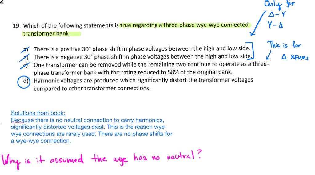
Hello, we’re working on the same problem set, but from book #2 now. We’ve got a question for problem #19 below.

The solution says that there is no neutral in the wye-wye transformer to carry harmonics. However, going back to the question.... we don’t see a mention of a wye with neutral. For problems like these, do we just assume no neutral?

Also, if there was a neutral, does this help to mitigate the harmonics?

a4a0a840a2974141e6d18676575788c3.jpg


ohfZuPEe.png.481d6a22fd1679e9e258a34a2cea5126.png

I drew two diagrams below; one for before the conductor break occurred and one for after. In the diagram before the break, the phase and neutral conductors are connected directly to the load. In the diagram after the break, the phase conductor is connected directly to the enclosure, and the neutral conductor connection is irrelevant (but it's still connected to the load). We don't need to worry about the neutral even though it's still connected to the load, because there is no power to the load since the phase conductor broke off. We only need to worry about the return path for current through the load's enclosure. So in the diagram after the break, the load inside the enclosure is drawn not connected. All current will flow through the enclosure. Since the enclosure is connected to ground, and the source's neutral is connected to ground, this will complete the circuit and will be the path for current. Once we calculate the current in the circuit, we can calculate the voltage at the enclosure by finding the resistance from enclosure-to-ground and multiplying it by the current.

Question on this one - Why is there a 0.1 ohm resistance in the equipment grounding conductor? Didn’t see it as a given in the problem - the problem specifically states “A single-phase load is connected phase-to-neutral and is feed from the source with each conductor, including the equipment grounding conductor, having a total resistance of 0.1 ohm”

It says “total resistance”... so why does the hot have a resistance of 0.1 ohm, and why does the EGC have a resistance of 0.1 ohm?
I think it makes more sense with a different wording of the question:

A single-phase load is connected phase-to-neutral. Each conductor has a total resistance of 0.1 ohms, including the equipment grounding conductor, .

 
Hello, we’re working on the same problem set, but from book #2 now. We’ve got a question for problem #19 below.

The solution says that there is no neutral in the wye-wye transformer to carry harmonics. However, going back to the question.... we don’t see a mention of a wye with neutral. For problems like these, do we just assume no neutral?

Also, if there was a neutral, does this help to mitigate the harmonics?

a4a0a840a2974141e6d18676575788c3.jpg
I honestly don't understand what he's trying to get at with this question.

We know delta-wye transformers are useful because the delta winding allows triplen harmonics to be contained within the transformer, reducing the harmonics on the wye side. Maybe he's assuming with a wye-wye transformer the harmonics are not contained within the transformer and are reproduced on the secondary side. I don't understand his solution of "because there is no neutral." Maybe he's implying that if the transformer had a neutral conductor the harmonics would flow in the neutral. However, I can't think of an instance where a wye connection would want to be used without a neutral. 

I don't like the question, but at least we can eliminated the a, b, and c answers.

 
Last edited by a moderator:
I honestly don't understand what he's trying to get at with this question.

We know delta-wye transformers are useful because the delta winding allows triplen harmonics to be contained within the transformer, reducing the harmonics on the wye side. Maybe he's assuming with a wye-wye transformer the harmonics are not contained within the transformer and are reproduced on the secondary side. I don't understand his solution of "because there is no neutral." Maybe he's implying that if the transformer had a neutral conductor the harmonics would flow in the neutral. However, I can't think of an instance where a wye connection would want to be used without a neutral. 

I don't like the question, but at least we can eliminated the a, b, and c answers.
These are the type of practice exam questions I run into once in a while that I just can't seem to quite get.  My first thought was, is it not safe to assume the Wye has a neutral?  I don't remember seeing any kind of sample or practice exam problem showing a Wye without one.  I've seen one example of a transformer bank arranged in delta, and you lose one and it asks you how it can be connected (open delta).  
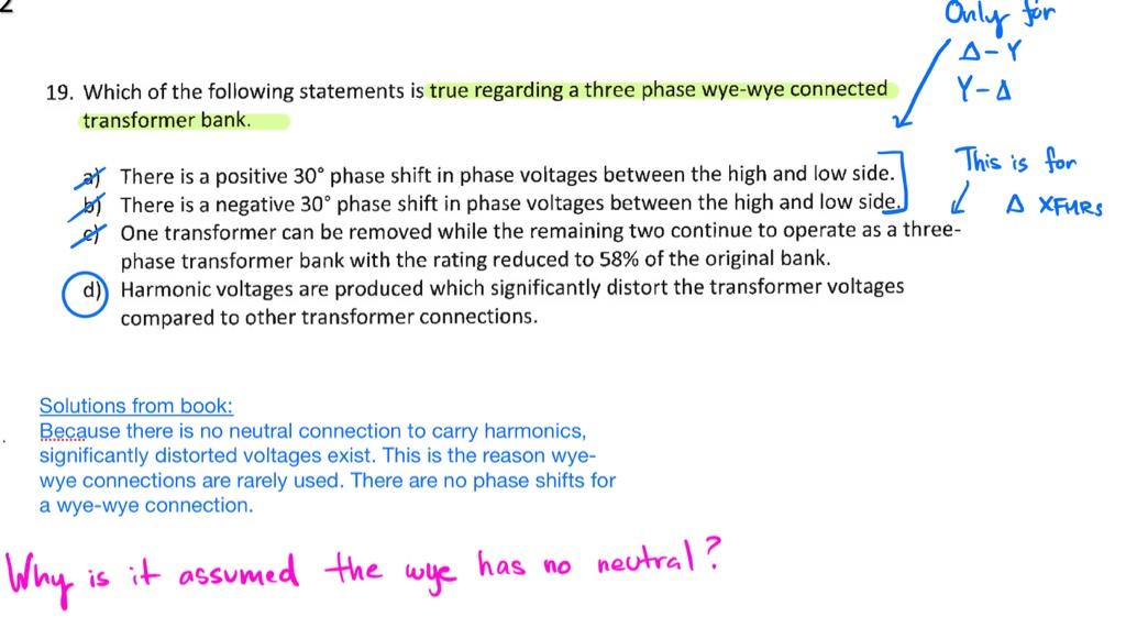
But examples like the one above I feel like I just have to move on, so I simply print it out with everyone's comments and put it in my binder and tag it in the rare event it might show up on the actual exam.

 
I honestly don't understand what he's trying to get at with this question.

We know delta-wye transformers are useful because the delta winding allows triplen harmonics to be contained within the transformer, reducing the harmonics on the wye side. Maybe he's assuming with a wye-wye transformer the harmonics are not contained within the transformer and are reproduced on the secondary side. I don't understand his solution of "because there is no neutral." Maybe he's implying that if the transformer had a neutral conductor the harmonics would flow in the neutral. However, I can't think of an instance where a wye connection would want to be used without a neutral. 

I don't like the question, but at least we can eliminated the a, b, and c answers.
I agree that he’s trying to get at the harmonics reduction with a delta-wye transformer, but is doing it backwards by giving the example of the wye-wye. I do not understand the “there is no neutral” comment either. In the delta-wye, you don’t have a neutral on the delta side and create a separately derived system on the wye side, but that is not what the solution seems to be saying. 

I don't mind the question, but the solution explanation leaves a lot to be desired. 

 
Another problem here, problem #21. We're at loss with the solution, as this is the first time we're seeing a relation between generator curves, to R-X diagrams, and to a distance relay. Does anyone understand the solution or is able to provide more clarity? 

Cram for PE Test 2 - #21 Problem.PNG

Cram for PE Test 2 - #21 Solution.PNG

 
Back
Top