
Zach Stone P.E.
Well-known member
This is part of a blog post originally posted on our free articles section at www.electricalpereview.com
You can read the entire article here in the original formatting: Free Articles: Impedance, Reactance, Admittance, Susceptance - Whats the difference?
This will be a great resource for anyone who has had any lingering questions with any of these terms.
Know that the most commonly confused terms are inductive reactance [[COLOR= rgb(51, 51, 51)]Ω][/COLOR] vs inductance [L], and capacitive reactance [[COLOR= rgb(51, 51, 51)]Ω][/COLOR] vs capacitance [F].
Feel free to print this out and add it to your references for the Electrical PE Exam.
The many “-tance” terms of Electrical Engineering
There are many different types of impedance components and they all rhyme, making it hard to remember which one is which.
Many even have the same units, which can lead to even further confusion.
Don’t let the same “-tance” ending fool you.
If you run into a question on the Electrical PE Exam that asks to solve for one of these components and you aren’t familiar with the exact differences, then you could end up bubbling the wrong answer even if your math and calculations are sound.
Chances are, you’ve already run into a similar mistake or headache while working sample exam practice problems.
To make sure this doesn’t happen on the exam day, let’s take a look at all the different components and define them, as well as understand where each comes from.
First
We’ll start with impedance (Z), a complex number, and take a closer look at both its real and imaginary components resistance (R) and reactance (X).
Second
We’ll deep dive a little further into both types of reactances, inductive reactance (XL) and capacitive reactance (XC).
Third
We will explore admittance (Y), another complex number, and take a closer look at both of its real and imaginary components conductance (G) and susceptance (B).
Impedance (Z)
Impedance is best described as the total opposition of the flow of current through a circuit when voltage is applied. Impedance is a complex number with both a real and imaginary component, it is represented by the capital letter Z, and has the unit of ohms [Ω].
Written in complex rectangular form, impedance looks like this:

Impedance is the sum of resistance (R) and reactance (X).
Resistance is the real component of impedance, or Re{Z} and reactance is the imaginary component of impedance, or Img{Z}.
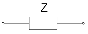
Impedance is typically represented in a circuit as either a block component:
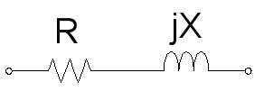
A resistive component with a positive inductive reactance:
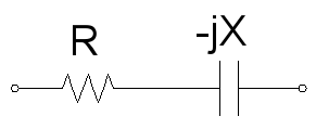
Or a resistive component with a negative capacitive reactance:
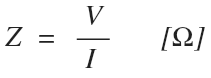
Impedance is most often calculated by re-writing ohm’s law to solve for Z:
Further recommended reading: https://en.wikipedia.org/wiki/Electrical_impedance
Resistance (R)
Like impedance, resistance also opposes the flow of current when voltage is applied. A purely resistive impedance lacks a reactive impedance component, such as a heating element, radiator, or a resistor.
Resistance is represented by the capital letter R, it is the real component of impedance Re{Z}, and therefore not a complex number, and the unit is ohms [Ω].
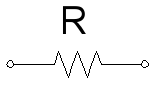
A resistance impedance component is represented in a circuit as a resistor:
Further recommended reading: https://en.wikipedia.org/wiki/Electrical_resistance_and_conductance
Reactance (X)
There are two types of reactance. Reactance will either oppose the change of current or voltage depending on which of the two types it is.
Inductive reactance will oppose the change of current.
Capacitive reactance will oppose the change of voltage.
Reactance is represented by the capital letter X, it is the imaginary component of impedance Img{Z}, and therefore not a complex number, and the unit is ohms [Ω].
Further recommended reading: https://en.wikipedia.org/wiki/Electrical_reactance
Inductive Reactance (XL) and Inductance (L)
Inductive reactance is one of two types of reactance, and is an imaginary impedance component that opposes the change of current. It is represented by the capital letter X with an L subscript and also has the unit of ohms [Ω].
Inductive reactance in ohms comes from angular frequency in radians per second, times inductance per unit length, times the total length of the component:

Where inductance is measured in total Henrys [H]:

And ω, the angular frequency in radians per second is found by multiplying the 2π times frequency:

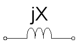
In a circuit diagram, inductive reactance is typically represented by a coil, since inductors are typically made by coiling a conductor into the shape of a solenoid.
Inductive reactance will always be a positive imaginary impedance component, or +jX.
inductive reactance resists the flow of current by the magnetic flux that builds around it.
An example of an inductive reactance would be a perfect ideal coil, like the windings in a motor or generator stator.
Further recommended reading: https://en.wikipedia.org/wiki/Inductance
Further recommended reading: https://en.wikipedia.org/wiki/Henry_(unit)
Capacitive Reactance (XC) and Capacitance (C)
Capacitive reactance is one of two types of reactance, and is an imaginary impedance component that opposes the change of voltage. It is represented by the capital letter X with a C subscript and also has the unit of ohms [Ω].
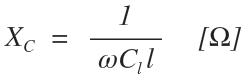
Capacitive reactance in ohms comes from the inverse of the angular frequency in radians per second, times capacitance per unit length, times the total length of the component:
Where capacitance is measured in total Farads [F]:

And ω, the angular frequency in radians per second is found by multiplying the 2π times frequency:
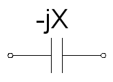
In a circuit diagram, a capacitive reactance is typically represented by the capacitor symbol, since capacitors are typically made up of two conducting plates that are separated by a dielectric medium.
Capacitive reactance resists the flow of voltage by the the buildup of charge between two conducting plates.
Capacitive reactance will always be a negative imaginary impedance component, or -jX.
An example of a purely capacitive reactance would be a perfect idea capacitor.
Further recommended reading: https://en.wikipedia.org/wiki/Capacitance
Further recommended reading: https://en.wikipedia.org/wiki/Farad
Admittance (Y)
Admittance is the opposite of impedance and as such, is best described as how easy a current can flow when voltage is applied, or how much current is admitted through the circuit. If impedance is more akin to current friction, than admittance would be comparable to ice or a slippery surface. Admittance is represented by the capital letter Y, and has the unit of siemens (S), and is a complex number.
Impedance is a complex number because it has both a real and imaginary value.
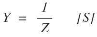
Written in complex rectangular form, admittance looks like this:

It is the sum of conductance (G) and susceptance (B).
Conductance is the real component of admittance Re{Y} and susceptance is the imaginary component of admittance Img{Y}.
Impedance is most often calculated by taking the inverse of impedance:
Ohm’s law can also be rewritten to use admittance instead of impedance to solve for both voltage and current:
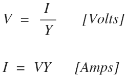
Impedance is most often represented by its admittance antinome when an impedance component is placed in a circuit such that it creates a shunt (parallel) least resistance path to ground, neutral, or another phase.
Since more current will flow through a path of least resistance (I=V/R), a shunt connection with a very small impedance means that the majority of current entering a shared node will flow through it rather than any other path.
Further recommended reading: https://en.wikipedia.org/wiki/Admittance
Conductance (G)
Conductance is the opposite of resistance, it is the real component of admittance Re{Y} and therefore not a complex number, it is represented by the capital letter G, and has the units of siemens (S).
Conductance is found by taking the inverse of resistance:
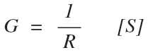
If resistance is the opposition of current, then conductance is how easily current can flow similar to our analogy of ice or a slippery surface compared to friction.
An easy way to remember the definition of conductance is by relating it to how well a circuit will conduct current.
Further recommended reading: https://en.wikipedia.org/wiki/Electrical_resistance_and_conductance
Susceptance (B)
Susceptance is the opposite of reactance, it is the imaginary component of admittance Img{Y} and therefore not a complex number, it is represented by the capital letter B, and has the units of siemens (S).
Susceptance is found by taking the inverse of reactance:
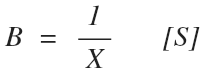
If reactance opposes the change of current or voltage, than susceptance is the quality of how easily current or voltage can change in a circuit.
An easy way to remember the definition of susceptance is by relating it to how susceptible a circuit is to the change of current or voltage.
Further recommended reading: https://en.wikipedia.org/wiki/Susceptance
You can read the entire article here in the original formatting: Free Articles: Impedance, Reactance, Admittance, Susceptance - Whats the difference?
This will be a great resource for anyone who has had any lingering questions with any of these terms.
Know that the most commonly confused terms are inductive reactance [[COLOR= rgb(51, 51, 51)]Ω][/COLOR] vs inductance [L], and capacitive reactance [[COLOR= rgb(51, 51, 51)]Ω][/COLOR] vs capacitance [F].
Feel free to print this out and add it to your references for the Electrical PE Exam.
The many “-tance” terms of Electrical Engineering
There are many different types of impedance components and they all rhyme, making it hard to remember which one is which.
Many even have the same units, which can lead to even further confusion.
Don’t let the same “-tance” ending fool you.
If you run into a question on the Electrical PE Exam that asks to solve for one of these components and you aren’t familiar with the exact differences, then you could end up bubbling the wrong answer even if your math and calculations are sound.
Chances are, you’ve already run into a similar mistake or headache while working sample exam practice problems.
To make sure this doesn’t happen on the exam day, let’s take a look at all the different components and define them, as well as understand where each comes from.
First
We’ll start with impedance (Z), a complex number, and take a closer look at both its real and imaginary components resistance (R) and reactance (X).
Second
We’ll deep dive a little further into both types of reactances, inductive reactance (XL) and capacitive reactance (XC).
Third
We will explore admittance (Y), another complex number, and take a closer look at both of its real and imaginary components conductance (G) and susceptance (B).
Impedance (Z)
Impedance is best described as the total opposition of the flow of current through a circuit when voltage is applied. Impedance is a complex number with both a real and imaginary component, it is represented by the capital letter Z, and has the unit of ohms [Ω].
Written in complex rectangular form, impedance looks like this:
Impedance is the sum of resistance (R) and reactance (X).
Resistance is the real component of impedance, or Re{Z} and reactance is the imaginary component of impedance, or Img{Z}.
Impedance is typically represented in a circuit as either a block component:
A resistive component with a positive inductive reactance:
Or a resistive component with a negative capacitive reactance:
Impedance is most often calculated by re-writing ohm’s law to solve for Z:
Further recommended reading: https://en.wikipedia.org/wiki/Electrical_impedance
Resistance (R)
Like impedance, resistance also opposes the flow of current when voltage is applied. A purely resistive impedance lacks a reactive impedance component, such as a heating element, radiator, or a resistor.
Resistance is represented by the capital letter R, it is the real component of impedance Re{Z}, and therefore not a complex number, and the unit is ohms [Ω].
A resistance impedance component is represented in a circuit as a resistor:
Further recommended reading: https://en.wikipedia.org/wiki/Electrical_resistance_and_conductance
Reactance (X)
There are two types of reactance. Reactance will either oppose the change of current or voltage depending on which of the two types it is.
Inductive reactance will oppose the change of current.
Capacitive reactance will oppose the change of voltage.
Reactance is represented by the capital letter X, it is the imaginary component of impedance Img{Z}, and therefore not a complex number, and the unit is ohms [Ω].
Further recommended reading: https://en.wikipedia.org/wiki/Electrical_reactance
Inductive Reactance (XL) and Inductance (L)
Inductive reactance is one of two types of reactance, and is an imaginary impedance component that opposes the change of current. It is represented by the capital letter X with an L subscript and also has the unit of ohms [Ω].
Inductive reactance in ohms comes from angular frequency in radians per second, times inductance per unit length, times the total length of the component:
Where inductance is measured in total Henrys [H]:
And ω, the angular frequency in radians per second is found by multiplying the 2π times frequency:
In a circuit diagram, inductive reactance is typically represented by a coil, since inductors are typically made by coiling a conductor into the shape of a solenoid.
Inductive reactance will always be a positive imaginary impedance component, or +jX.
inductive reactance resists the flow of current by the magnetic flux that builds around it.
An example of an inductive reactance would be a perfect ideal coil, like the windings in a motor or generator stator.
Further recommended reading: https://en.wikipedia.org/wiki/Inductance
Further recommended reading: https://en.wikipedia.org/wiki/Henry_(unit)
Capacitive Reactance (XC) and Capacitance (C)
Capacitive reactance is one of two types of reactance, and is an imaginary impedance component that opposes the change of voltage. It is represented by the capital letter X with a C subscript and also has the unit of ohms [Ω].
Capacitive reactance in ohms comes from the inverse of the angular frequency in radians per second, times capacitance per unit length, times the total length of the component:
Where capacitance is measured in total Farads [F]:
And ω, the angular frequency in radians per second is found by multiplying the 2π times frequency:
In a circuit diagram, a capacitive reactance is typically represented by the capacitor symbol, since capacitors are typically made up of two conducting plates that are separated by a dielectric medium.
Capacitive reactance resists the flow of voltage by the the buildup of charge between two conducting plates.
Capacitive reactance will always be a negative imaginary impedance component, or -jX.
An example of a purely capacitive reactance would be a perfect idea capacitor.
Further recommended reading: https://en.wikipedia.org/wiki/Capacitance
Further recommended reading: https://en.wikipedia.org/wiki/Farad
Admittance (Y)
Admittance is the opposite of impedance and as such, is best described as how easy a current can flow when voltage is applied, or how much current is admitted through the circuit. If impedance is more akin to current friction, than admittance would be comparable to ice or a slippery surface. Admittance is represented by the capital letter Y, and has the unit of siemens (S), and is a complex number.
Impedance is a complex number because it has both a real and imaginary value.
Written in complex rectangular form, admittance looks like this:
It is the sum of conductance (G) and susceptance (B).
Conductance is the real component of admittance Re{Y} and susceptance is the imaginary component of admittance Img{Y}.
Impedance is most often calculated by taking the inverse of impedance:
Ohm’s law can also be rewritten to use admittance instead of impedance to solve for both voltage and current:
Impedance is most often represented by its admittance antinome when an impedance component is placed in a circuit such that it creates a shunt (parallel) least resistance path to ground, neutral, or another phase.
Since more current will flow through a path of least resistance (I=V/R), a shunt connection with a very small impedance means that the majority of current entering a shared node will flow through it rather than any other path.
Further recommended reading: https://en.wikipedia.org/wiki/Admittance
Conductance (G)
Conductance is the opposite of resistance, it is the real component of admittance Re{Y} and therefore not a complex number, it is represented by the capital letter G, and has the units of siemens (S).
Conductance is found by taking the inverse of resistance:
If resistance is the opposition of current, then conductance is how easily current can flow similar to our analogy of ice or a slippery surface compared to friction.
An easy way to remember the definition of conductance is by relating it to how well a circuit will conduct current.
Further recommended reading: https://en.wikipedia.org/wiki/Electrical_resistance_and_conductance
Susceptance (B)
Susceptance is the opposite of reactance, it is the imaginary component of admittance Img{Y} and therefore not a complex number, it is represented by the capital letter B, and has the units of siemens (S).
Susceptance is found by taking the inverse of reactance:
If reactance opposes the change of current or voltage, than susceptance is the quality of how easily current or voltage can change in a circuit.
An easy way to remember the definition of susceptance is by relating it to how susceptible a circuit is to the change of current or voltage.
Further recommended reading: https://en.wikipedia.org/wiki/Susceptance
Last edited by a moderator:

