Help With Per-Unit Impedance Base conversion

Professional Engineer & PE Exam Forum

Help Support Professional Engineer & PE Exam Forum:

This site may earn a commission from merchant affiliate links, including eBay, Amazon, and others.

wfg42438

Active member
Joined
Feb 13, 2022
Messages
34
Reaction score
2
Hello,

I was looking at the sample PE exam question below.

MVA_2_kpwaku.png


MVA_1_ey2iur.png


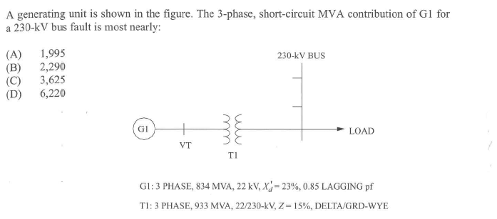
When solving the question i decided to use the XFMR Secondary voltage and MVA as my base values.

Which then required the Gen imp to be converted to the XFMR MVA base.

When doing so the first time i followed the process below:

Vbase=230kV, MVA Base=933 MVA

Ibase= MVA Base/ Sqrt(3) * Vbase

Zgen_933MVA= Zgen_834MVA * (kV old/KV_New) * (MVA new/MVA Old) = (0.23)*(22/230)^2 * (933/834)

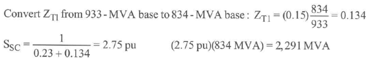
However, after looking at the solution i see that the voltage conversion is not necessary.

If i remove the voltage conversion ratio then my answer matches the MVAsc from the solution.

Can anyone clarify when the voltage transformation is indeed applicable and touch on why its not applicable in this case?
 
Also, to answer your question, base voltage at transformer secondary is 230 kV. kV_b=230kV. This is equal to the transformer secondary voltage. kV_new=230kV and kV_old=230kV, so the ratio is 1.
Read the article from the above link and everything will be clear.
 
Also, to answer your question, base voltage at transformer secondary is 230 kV. kV_b=230kV. This is equal to the transformer secondary voltage. kV_new=230kV and kV_old=230kV, so the ratio is 1.
Read the article from the above link and everything will be clear.
But isn't the Genarators impedance based on the Gens MVA and voltage base which in this case is 22kV ?
 
But isn't the Genarators impedance based on the Gens MVA and voltage base which in this case is 22kV ?
Sorry, I thought you were asking about the transformer. Yes, for generator, kV_base=22kV. Here is the breakdown of the process:

When you select a base MVA, this will be same for all components. So, both transformer and the generator has same base MVA.
On the other hand, base kV will not be same for all components. You need to pick base voltage for each voltage zone.

Draw an imaginary line from the center of the transformer. You now have two voltage zones, Zone 1 on the left of the imaginary line (22kV) and Zone 2 on the right (230kV).

Let's select generator's MVA as base. MVA_base=834 MVA( You can choose any value as base if the problem does not specify it). For Zone 1, kV_base=22kV

MVA_old and kVA_old are the given values of the generator, in this case 834 MVA and 22kV. MVA_new is what you select as base MVA, in this case 834 MVA. kV_new is your base voltage. In this case, 22kV.

Now use these values in Znew=Zold(....), the ratio will be 1 for both MVA and kV, so Znew=Zold=0.23 for G1.

Now, for transformer, you can use either primary side or the secondary side to calculate it's impedance. In this case, let's use the secondary side.
Here, MVA_base=834 MVA(same for all components), and kV_base=230kV

MVA_old=933MVA( transformer's MVA), kV_old= 230kV (tr. secondary voltage)
MVA_new=834 MVA( your base MVA), kV_new= 230kV(your base kV).

Use above values in formula, Znew=Zold (.....), you will get Znew= 0.134.
 
Last edited:
Also, keep in mind that the voltage ratio may not always cancel, say, if the actual voltage on the primary side of the transformer is not equal to the transformer's voltage ratio.
 
If you use transformer's MVA as base MVA, for transformer, Znew=Zold=0.15 pu (both kV and MVA ratio is 1).
For generator, Znew= 0.23*(22/22)^2*(933/834) (because kV_new=kV_old=22kV)
 
Sorry, I thought you were asking about the transformer. Yes, for generator, kV_base=22kV. Here is the breakdown of the process:

When you select a base MVA, this will be same for all components. So, both transformer and the generator has same base MVA.
On the other hand, base kV will not be same for all components. You need to pick base voltage for each voltage zone.

Draw an imaginary line from the center of the transformer. You now have two voltage zones, Zone 1 on the left of the imaginary line (22kV) and Zone 2 on the right (230kV).

Let's select generator's MVA as base. MVA_base=834 MVA( You can choose any value as base if the problem does not specify it). For Zone 1, kV_base=22kV

MVA_old and kVA_old are the given values of the generator, in this case 834 MVA and 22kV. MVA_new is what you select as base MVA, in this case 834 MVA. kV_new is your base voltage. In this case, 22kV.

Now use these values in Znew=Zold(....), the ratio will be 1 for both MVA and kV, so Znew=Zold=0.23 for G1.

Now, for transformer, you can use either primary side or the secondary side to calculate it's impedance. In this case, let's use the secondary side.
Here, MVA_base=834 MVA(same for all components), and kV_base=230kV

MVA_old=933MVA( transformer's MVA), kV_old= 230kV (tr. secondary voltage)
MVA_new=834 MVA( your base MVA), kV_new= 230kV(your base kV).

Use above values in formula, Znew=Zold (.....), you will get Znew= 0.134.

Thank you for the detailed explanation.

Let me just ask the following to make sure i understand this correctly:
1. When we select the BasekV this should represent the faulted bus voltage right?
2. Lets assume the question asks instead for the 3P fault current at "VT"
Would this be the correct process if i assume BaseMVA=834 MVA (Gen MVA) and BasekV=GenkV=22kV

Zg1= 0.23
ZXFMR= ZFMR_Old*( 230kV/22kV) ^2 *( Gen_MVA/XFMR_MVA)
1. Select transformer's voltage rating as base values. In above example, the faulted bus is on the transformer secondary. So, Vbase at that zone is 230kV.

There are some cases where source voltage does not match the transformer's voltage. For e.g. if the source was 20 kV and the transformer was rated 22kV/230kV. But I would not worry about it for now. I think the chances of getting those kind of problems in PE exam are low. Once you understand the pu method properly, then you can look at those cases.

2. If the 3ph fault was at VT, you would not need to calculate the impedance of the transformer. You only calculate the impedance up to the fault point, not beyond it because the short circuit current is limited by the impedance up to the fault point.

You should also check MVA method of calculating 3ph fault current. It is easier than the pu method.
 
Last edited:
1. Select transformer's voltage rating as base values. In above example, the faulted bus is on the transformer secondary. So, Vbase at that zone is 230kV.

There are some cases where source voltage does not match the transformer's voltage. For e.g. if the source was 20 kV and the transformer was rated 22kV/230kV. But I would not worry about it for now. I think the chances of getting those kind of problems in PE exam are low. Once you understand the pu method properly, then you can look at those cases.

2. If the 3ph fault was at VT, you would not need to calculate the impedance of the transformer. You only calculate the impedance up to the fault point, not beyond it because the short circuit current is limited by the impedance up to the fault point.

You should also check MVA method of calculating 3ph fault current. It is easier than the pu method.
Thank you so much!

In your example where the source kV and XFMR primary kV dont match what would decide the base kv in that case?

For the VT example i completely follow what you are saying. However if there was a load on the XFMR secondary for example then would my XFMR impedance transformation be valid?
Select transformer's primary as base kV. Now the Vpu of source will not be 1, it will be Vpu=Actual Voltage/Base Voltage=20kV/22kV=0.9 pu

Calculate the impedance up to fault point only. If the fault is at VT, you do not need to calculate the impedance beyond that fault point.
 
Back
Top