Truss Design

Professional Engineer & PE Exam Forum

Help Support Professional Engineer & PE Exam Forum:

This site may earn a commission from merchant affiliate links, including eBay, Amazon, and others.

medeek

Active member
Joined
Mar 18, 2013
Messages
39
Reaction score
1
Location
Copalis Beach, WA
I've recently started working on a small web based app that can be used to design and analyze common wood trusses. I intend to add more in depth sizing logic after further study of the TPI 1-2007. Does anyone know of any other good resources for trusses and truss design?

The proto-type app is currently here:

http://design.medeek.com/calculator/calculator.pl

I'm writing it in Perl with a MySQL backend if necessary.

I'm also trying to decide between LRFD or ASD analysis, or perhaps both. Perhaps someone could weigh in on which method would be best for truss design, I've seen example of both.

 
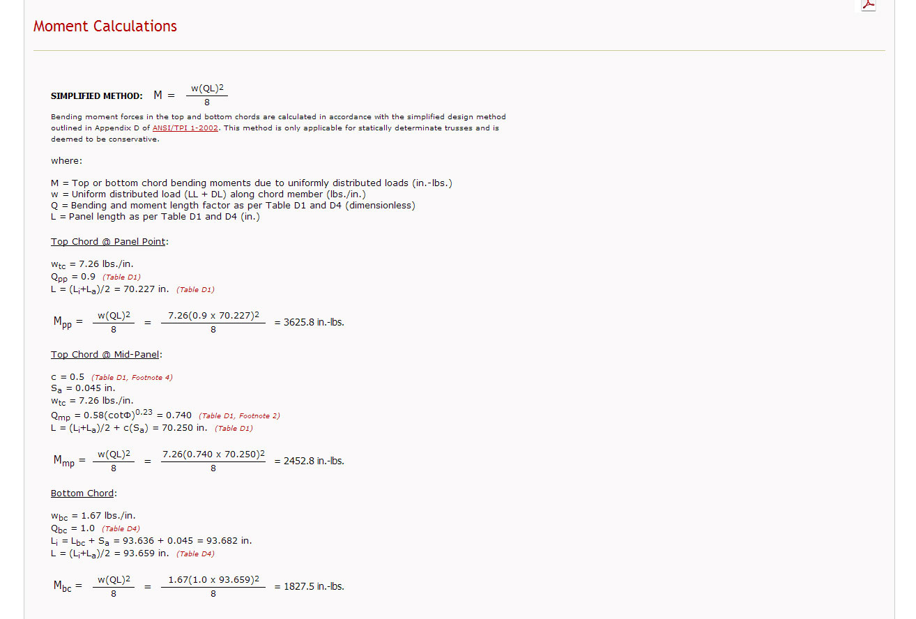
I've kind of hit a road block on the moment calculations. The current spec TPI 1-2007 calls for using the matrix method in determining the moments. However, I need to be able to run this app without doing a full blown analysis using RISA or some other FEA type product. For now I've gone with the simplified method which is the method used in the TPI 1-1995 standard, at least I can produce a solution. Typical result below:

fink_moments.jpg


If anyone has any ideas on how to do a simple matrix method analysis of a common fink truss please send me in the right direction. My biggest unknown with this would be how to deal with the fixity of joints at panel points and heels. I've just ordered a copy of Hibbeler's Structural Analysis to further research how best to deal with frames, trusses etc...

One thing I found really helpful was the samples provided in the previous editions of the TPI 1, its really quite disappointing to see no such example calculations in the current standard.
 
I'm also looking for anyone who would be interested in collaborating on this project. I need someone who has some civil/structural engineering experience and preferably some experience coding Perl.

 
With a little help from a text called "Design of Wood Structures" by Donald E. Breyer and a recently purchased copy of the NDS 2012, the equations in TPI 1 finally made a lot more sense. I will say this has been quite an education with regards to structural design of wood structures. Last night I finally completed the full lumber analysis for the fink truss. Top and Bottom chords as well as all the webs. Now its time to start working on the heel joint check and all of the connector plates. Wind loads might be next but I need to research this quite a bit more.

After doing some reading on trusses it seems that the simplified method of calculating moments should be fine for statically determinate common trusses such as a fink, howe, king or double fink truss. Its when you start trying to analyze the statically indeterminate variety (ie. attic trusses) then the simplified method really comes up short. For that I will need RISA integration with the app.

 
I have given this some thought and the goal of this app in its final incarnation is the following:

This application is intended to be used primarily by Design Professionals (architects, engineers, etc.), Building Code Officials, Contractors and Inspectors with the goal of helping everyone that uses it to more easily understand the loads, parameters, calculations and limitations of a given common truss design. By changing geometry and loading parameters multiple design scenarios can be quickly compared and analyzed, hopefully providing a benefit to the design professional. However, let it be noted that this application is purely a tool to be used, similar in concept to that of a calculator or estimator.

The designing and engineering of trusses should not be controlled by "plate manufacturers" it should be controlled by architects and engineers.

The plate manufacturers will only sell/lease their software to truss plants and not to licensed architects and engineers who could actually benefit from their software in the design and planning stages of many residential, commercial and agricultural structures.


In creating this app I am also hoping to force the plate manufacturers to release a version of their software that is for use by architects and engineers.

I contacted both Alpine and Mitek a few months ago and was hoping to purchase or lease their software as I designed some new detached garages. Their answer to me was that they did not want their truss products becoming a commodity so they would not let anyone access their software except for authorized truss manufacturers who also purchased their plates.

The design of metal plated connected wood trusses in America is essentially a black box to most practicing engineers and architects.

I intend to change this.
 
This is a fantastic idea. If I knew more about coding, I'd help out. Sadly, I don't.

If you don't mind a (probably headache-inducing) suggestion - point loads (both top and bottom chord) would be handy, as would lateral/axial chord loads.

 
I am in the process of figuring out how to also add unbalance wind loads to the analysis, is that what you are requesting with the lateral loads above?

Point loads on the top and bottom chord could easily be added but I'm trying to come up with a general solution for checking the trusses specs (lumber, plates, bracing etc...) rather than a very specific loading case. However, I will give this some more thought.

I don't need help in the coding dept. as much as I need help currently with figuring out chapter 8 of the TPI 1-2007. The plate sizing and checking as outlined in this chapter is very confusing in some parts, in my opinion. I would really like to get my hands on some sample calculations that completely walk through the plate sizing calcs for a standard fink truss if such a thing is out there.


No, though it's helpful. I'm thinking in terms of drag trusses, where a single roof truss distributes the diaphragm load to a wall below via a DSC2 or DSC5 connector. Or, if your analysis allows parallel chord trusses, where a shear wall above is connected to an in-plane offset shear wall. But in that situation you would also need to calculate based on multiple point loads for multiple cases, which could get bothersome.

 
After about a good week of solid programming and scratching my head I've finally managed to add the requisite Matrix Analysis to my Truss Calculator. Thank-you R.C. Hibbeler for your Structural Analysis text on the subject (ch. 14 - 16), if the subject had not clearly laid out in front of me I would never have figured out the numerous steps to arrive at the solutions.

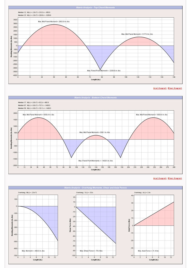
Here is an example of the output of my matrix analyzer for the Fink truss:

fink_matrix.jpg


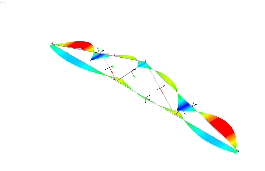
I've even inserted the correct code to account for the additional loading/moments if there are overhangs. I double checked my work by modeling up identical trusses (beams and trusses members) in both Strand7 and Solidworks (COSMOS/Simulator). My result were within 1.5% or better, so I'm really happy about that.

My only concern with my analysis is how correct my analog for the truss really is. What I mean is that the bending moments are heavily influenced by the amount of rigidity of the joints. Fixing the joints (where chords meet) or pinning them dramatically affects the bending moments and even the axial and shear loads to some extent. My analog model is basically rigid at the heel and peak joints and pinned at all other web-to-chord or web-to-web joints. This seems to approximate most closely the moments calculated using the simplified method (pre TPI-2002).

What I also found quite interesting (and expected) is if you use a stronger type of lumber on the top chord as compared to the bottom chord. The top chord loads increase and the bottom chord loads decrease. The matrix analysis is almost as good as FEA. It's really quite cool to be able to calculate something like this just using a bunch of matrices.
 
Leaving the peak joint as a rigid connection without exploring the implications of a pinned or semi-rigid joint seem like a cop-out to me so I spent most of the day attempting to release the peak joint so that it could act as a pinned (zero moment transfer) joint. For the web members I accomplished a similar task by altering the 6x6 stiffness (k') matrix so that it only included the axial terms, thereby eliminating any shear or moment forces, making these members axial only or simple pinned truss members. However, for the top chord members it was not such an easy task. I initially tried eliminating the row of the matrix that was responsible for the far end moments (pinned end), but it some became apparent that the interplay between moments and shear forces was more than I had originally thought. I was about to accept defeat but then after spending a couple more hours digging about online I came upon a gem of a paper published in 2010 in the Electronic Journal of Structural Engineering by M. E. Kartal. This paper outlined a couple of methods for obtaining the correct stiffness matrix for semi-rigid connections. With this information I was then able to add in feature so that one can select whether the peak joint is rigid, semi-rigid or pinned.

I then tested it for accuracy against an identical model in Solidworks Simulator for both the pinned and rigid connection at the peak joint with near perfect results. Unfortunately, Solidworks does not allow for adjusting the rigidity of connections between beams in its interface so I currently do not have the tools to test the accuracy of the semi-rigid model. However it appears to present the correct trends when compared against the other two options. If someone has a copy of ANSYS or some other reasonably high end FEA software I would be interested to see how well it will compare with third party verification.
 
I've read a number of papers the last couple of days. Many of them I found via the footnotes in the TPI-1 2007 standard. Based on what I've read I've been able to form the following conclusions, correct me if any of these seem incorrect or need further discussion.

1). Web member joints connecting to other web member and chords are best modeled as pinned. Assuming a signficant moment transfer at the web joints will cause one to underestimate the moments present in the chords.

2). As Mr. Tangren suggests the joints and splices on chord members cannot be modeled as simple pin joints and should be modeled at a min. as semi-rigid. The TPI gives an equation for determining the max. allowable moment (very long cumbersome equation, more on this later) but does not seem to clearly address how much rigidity at the joint(s) to assume, except for a pinned joint with eccentricity in the axial loading.

3). Matrix Analysis is the best and easiest way to analyze the axial, shear and moments present in a truss. The real question is how best to create the truss analog. Setting up matrix analysis is really not that bad once you've figured it out once. I initially was using Excel spreadsheets but then I found a Perl module (MatrixReal) that made most of my matrix operations a snap. My results agree with third party programs (Solidworks, Strand7) to within 1.5% which gives me a high degree of confidence.

4). I am analyzing the truss axial loads using both the classic pinned connection model and the matrix analysis. The matrix analysis values are typically higher loads 5-8% on average.

 
I'm now attacking the plate design for each joint. Specifically for a common fink truss. After reviewing chapter 8 of the TPI standard and looking at all the requirements I'm again at a standstill as I try to understand how to correctly apply the moment check equation at the peak joint of this truss type. The equation is ridiculously complex or at least appears that way at first glance. I am looking for a sample problem that show the application of this equation to either a chord splice or peak joint.

Ma = Cm{T1(Wp y z-d1) T2(4Wp 2y 4z-3d1)/3 Cs(d1-z-y) Cw(d1-y)}/5

In particular I'm a little confused how to assign the correct values to determine "y" the distance from the neutral axis to the wood edge with this peak joint configuration. "y" being given by:

y = {t1R1[Fy(1.8z Wp) Fu(Wp z)] - 2Pt}/ {d2C t1R1(1.8Fy Fu)}

If I measure z from the wrong direction this entire expression will be incorrect.

 
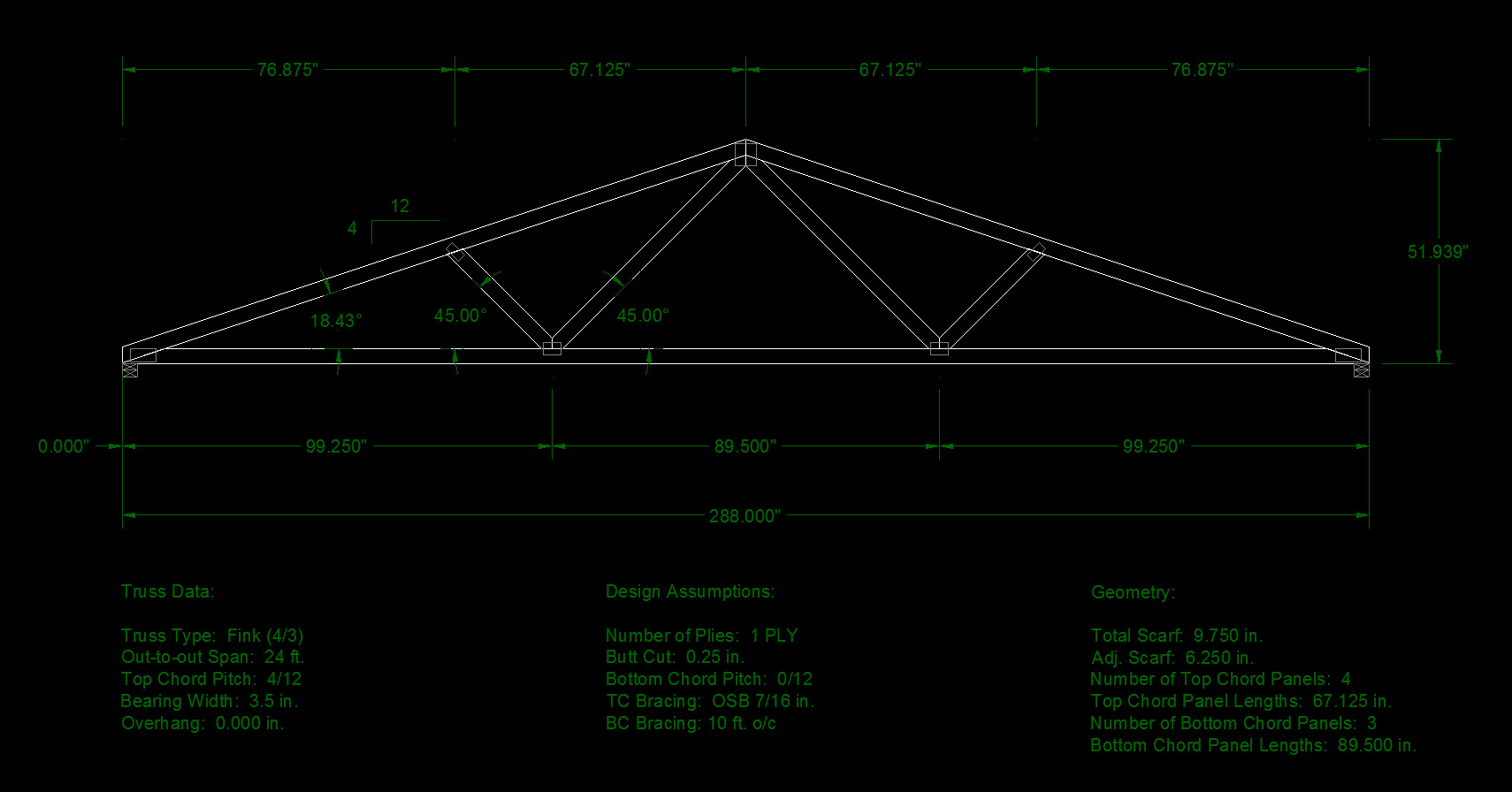
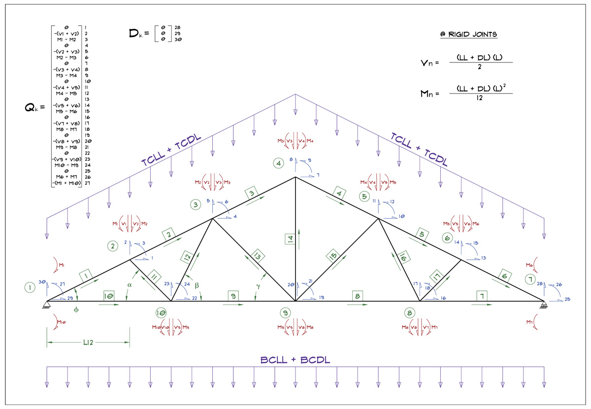
Starting to work on the modified queen truss, here is the schematic for the matrix analysis of it. The structure stiffness matrix will be a 30 x 30 matrix (900 values), its no wonder they didn't do this sort of thing prior to our modern computers, imagine trying to calculate this by hand. :)

MODQUEEN_MATRIX.jpg


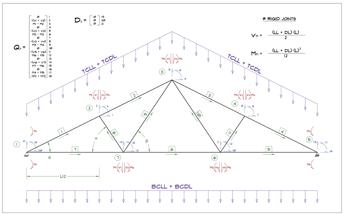
Compare this to the fink truss, which has a few less webs and hence the computations are less 21 x 21 matrix (441 values)

FINK_MATRIX.jpg

 
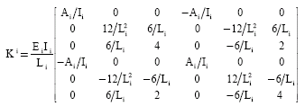
These schematics really say nothing about which members are pinned, semi-rigid or rigidly connected. The stiffness matrix (k) for each member is what determines that.

eq7-2k9-3906-3911.gif


In my analysis I am treating all of the webs as pinned jointed on both ends and only capable of transferring axial loads (classical truss members). The top and bottom chords at panel points are treated as rigid connections. The peak joint is treated either as rigid, pinnned or semi-rigid, this is user configurable. The heel joint is treated as rigid or semi-rigid. My reasoning and justification for these model settings is based on a number of papers I have compiled on the rigidity of joints of MPC wood trusses. I have saved each one and will compile a reference list at some point to accompany the truss designer documentation.

These two papers especially the bottom one were quite helpful:

http://design.medeek.com/resources/truss/DOCUMENTS/Paper_124.pdf

http://design.medeek.com/resources/truss/DOCUMENTS/20103.pdf
 

Latest posts

Back
Top