Bridge Design Check

Professional Engineer & PE Exam Forum

Help Support Professional Engineer & PE Exam Forum:

This site may earn a commission from merchant affiliate links, including eBay, Amazon, and others.

civengPE

Well-known member
Joined
Jun 2, 2006
Messages
317
Reaction score
3
Location
Houston, Texas
I have a spot on some property that my wife and I own that I need to build a simple bridge to cross. I have not had to do any real structural analysis in a long time and was hoping someone on here would take pity on me and take a look at what I am proposing to do.

I have attached some rough drawings for the bridge, but in a nut shell:

  • I need to be able to cross in a small pick up (Ford Ranger)
  • Open Span of about 30'
  • I was planning to install 5 ea 6"X6" treated posts on both sides of the bridge with 2"X10"X30' bolted on both sides of the 6"X6"
  • At the 1/3 span points I would have another 6"X6" angled back to the bank
  • The decking would be 2"X6" with 1/4" gap in between
  • Assume no soil issues

I would have liked to install a culvert and just fill it in, but it will not work. I would really like to know if A) the bridge is under designed and what I might be able to do to improve it or B ) if it is way over designed and where I could cut back to save some money or C) it's perfect! :party-smiley-048:

I appreciate your help in advance and please be gentle in criticizing my drafting abilities. :dunno:

Bridge_Design.pdf


Attachments

  • Bridge_Design.pdf
    195.8 KB
did you do any calculations or are you just going on gut, look and feel?

What do you base assume "no soil issues"?

Why won't a culvert work?

 
Last edited by a moderator:
did you do any calculations or are you just going on gut, look and feel?
What do you base assume "no soil issues"?

Why won't a culvert work?
A culvert wont work, because it is in the woods and is going to get choked with debris the first time we get a big rain. I have had problems in other areas on the property from this in much smaller creeks. I have done some calculations, but honestly have absolutely zero experience with timber structures. My fuzzy math says this should work, but I was hoping that someone that does this all of the time would be able to take one glance at it and say yea or nay. As far as the soil comment goes, I was just trying to head off the questions regarding soil borings, conditions etc... I am not worried about the soil, just the structure itself.
I'm structural but don't have a lot of expereince with timber stuff. Do you have access to a copy of the NDS? It's pretty straight forward and should let you know if you're in the ballpark.

good luck

 
Unfortunately, I do not. I will try to find some more resources on line.

Does anyone know the maximum allowable bending moment on a yellow pine 6"X"6?

 
Download FM 5-170 and take a look at the bridge classification procedure. You should be able to validate your design quickly enough. I recall placing timber supports in concrete or in earth is a bad idea especially because of deterioration of wood due to moisture.

 
I will download it as soon as I get back to the office. The real problem I am having is finding the allowable bending moments for timber members.

The wood I am using is rated for under ground / water contact.

BTW I have a simpler design I am working on right now that should be much easier / cheaper to install.

 
Last edited by a moderator:
ASD Member capacity

6-inch nominal thickness (5.5 inch dry dressed size) C subD =1.0 C subL = 1.0

Southern Pine 6x6

Select structural M' = 41.6 in-kip

No. 2 M' = 23.6 in-kip

ref NDS (2005)

 
Using the numbers you gave me (assuming no Fs was built in) my new design has a Fs of 3.14 on the beams and 2.0 on the columns. Thanks you guys for your help.

I'll take some pictures of it after I complete building it in a few weeks.

 
those numbers are ASD Allowable Stress Design a/k/a working stress so the FSis "built-in". I assume you noted the distinction between "select structural" and "No. 2" materials

Make sure you includde some dynamic load allowance (impact) to your vehicle loads (typically 30-50%).

 
Last edited by a moderator:
those numbers are ASD Allowable Stress Design a/k/a working stress so the FSis "built-in". I assume you noted the distinction between "select structural" and "No. 2" materials

Make sure you included some dynamic load allowance (impact) to your vehicle loads (typically 30-50%).
I completely changed my design, because it depended on being able to find 2X8X30's. I now have 6X6 columns (5 ea at the ends and 1/3 points) as well as 6X6X8' beams tied together at the columns. The 1/3 point columns now just go straight down instead of angling back on a 45. I would upload a drawing, but our scanner is down here at work today.

I never used ASD we always used LRFD in college which used load factors to build up the safety factors. I used the #2 values you provided assuming no "built in" safety factor and got 3 times the required strength on the beams. If I factor in the ASD Fs values It would be even better. I could dial back the design some, but the cost savings would not be all that great so, I will take the extra Fs.

I am meeting with my contractor on Friday and am hoping to have this thing done in the next couple of weeks.

 
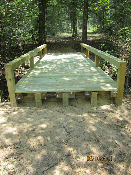
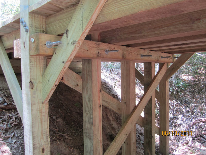
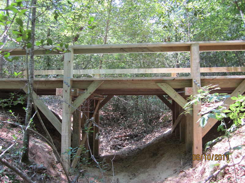
Here are some photos of the finished product. All in all it turned out better than I expected, but the contractor did mess up a little on the beam placement. He installed them on the inside of column #s 2&4 instead of the outside like I detailed. I think it will be fine and we can fix that if it turns out to be an issue.

IMG_0289.JPG


IMG_0293.JPG


IMG_0292.JPG


Latest posts

Back
Top