Voltage drop problem

Professional Engineer & PE Exam Forum

Help Support Professional Engineer & PE Exam Forum:

This site may earn a commission from merchant affiliate links, including eBay, Amazon, and others.

BamaBino

Well-known member
Joined
Nov 16, 2008
Messages
156
Reaction score
0
Location
north Alabama
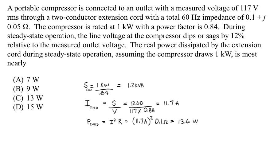
The answer is suppose to be C.

Do y'all agree with my solution?
32.jpg


Thanks for posting this. I just thought of a question. I am tempted to simply assume the voltage across the cable is 117V-102.96V = 14.04V, but assuming your answer is right, then it must instead be IR = (11.56)(0.1) = 1.156V, and can also use V^2/R, or IV to get the power in the cable.

I believe I am misunderstanding something about the voltage across the cable. Why is it 1.156V and not 14.04V?

Thanks

ETA: OK, I realize that in this case Ohms law is not V=IR but V=IZ, but there is still something strange going on here.

 
Last edited by a moderator:
The solution given is correct. The extension cord impedance has a problem though. Dropping 14 volts across an impedance of approximately 0.1 ohms will require over 100 amps.

 
The solution given is correct. The extension cord impedance has a problem though. Dropping 14 volts across an impedance of approximately 0.1 ohms will require over 100 amps.
So is our conclusion that the cable is not sized properly, resulting in too high of a voltage drop? To me, 14V makes sense for starting, but not for running.

ETA: I guess you mean that the impedance and voltage drop numbers don't make sense relative to each other, but using the load current in conjunction with the given impedance does give the answer that has been listed. So this may not be the best problem in the world to learn circuit analysis from.

 
Last edited by a moderator:
My take on this is the question is worded poorly. It could be that the 117 volts is at the outlet before the circuit is loaded by starting the compressor. Outlets are generally not infinite sources, so once the compressor starts, the outlet voltage probably drops as well--but they don't really make that clear in the problem statement.

Following this logic through, the voltage drop over the cord would be the 1.156 V R2KBA calculated and the rest of the 14 V drop is upstream of the outlet. Or, the voltage at the outlet is ~104 V after the motor is started.

 
I emailed the author of the problem and he was kind enough to reply.

Below is his reply. I haven't tried reworking the problem.

me> If it is worked differently by using the 14 volts dropped in the extension

me> chord with an impedance of approximately 0.1 ohms that will require over 100

me> amps. Am I seeing that wrong?

The voltage at the inlet is not in-phase with the

voltage at the compressor--therefore, you should be careful about

subtracting only the amplitudes of _phasor_ voltages!! After you

determine the possible phase(s) voltage at the compressor, using the

power factor and line impedance, then subtracting the inlet phasor

voltage from the compressor phasor voltage.

 
The voltage at the inlet is not in-phase with the voltage at the compressor--therefore, you should be careful about

subtracting only the amplitudes of _phasor_ voltages!!
Ok, I'll play his game:

Cable impedance 0.1+j0.5 = 0.112/26.6o

Given: 1kW at 0.84pf

S=1kw/0.84=1.2kVA/32.9o

S=VI* where V is 117-12%=102.96V/0o. (For simplicity, I'm calling the compressor voltage the 0 degree reference.)

I*=S/V=1.2kVA/32.9o/102.96V/0o=11.65/32.9o

I=11.65/-32.9o

VOutlet = VCompressor+VCable

VCable=IZ = (11.65/-32.9o)(0.112/26.6o) = 1.305/-6.3o

VOutlet is then 102.96V/0o+1.305/-6.3o=104.26/-0.08o

Double-check my math, but I think my comment that a much greater current is required on that cable to get that voltage drop still stands.

 
Last edited by a moderator:
Back
Top