I understand how they get the solution but I don't understand why they didn't include the (10+j0) Ohm/Phase load as part of the load current. I am assuming it is because it is part of the transmission line current. Any ideas?

You are using an out of date browser. It may not display this or other websites correctly.
You should upgrade or use an alternative browser.
You should upgrade or use an alternative browser.
NCEES #118
- Thread starter threatta
- Start date
Help Support Professional Engineer & PE Exam Forum:
This site may earn a commission from merchant affiliate
links, including eBay, Amazon, and others.
Flyer_PE
Jr. PE / Sr. Company Pilot
The load impedance only matters if you are trying to determine the load current. The problem gives you the transmission line current directly. All you need to do then is determine the current on the generator side of the 13.2-132 kV transformer. Given the transmission line current, the only thing you need to solve the problem is the turns ratio of that transformer. All other information given is superfluous.
Ok. Pretty much as I figured. Thanks!The load impedance only matters if you are trying to determine the load current. The problem gives you the transmission line current directly. All you need to do then is determine the current on the generator side of the 13.2-132 kV transformer. Given the transmission line current, the only thing you need to solve the problem is the turns ratio of that transformer. All other information given is superfluous.
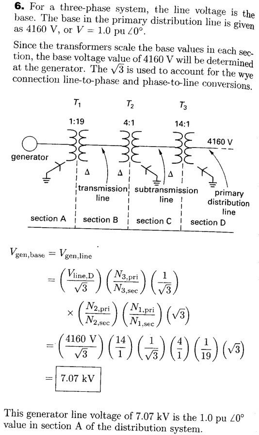
I can't remember, but I think someone mentioned that when the problem stated that it is a single-phase transformer, you would use the square root of three different for delta-wye or wye-delta calculation, and not for a three phase transformer. Is that a true statement? Meaning that this problem stated it's a 3-phase transformer, and so you don't need to taking into account the square root of three.
Flyer_PE
Jr. PE / Sr. Company Pilot
It all depends on how the data is presented to you.
When you are presented with a 3-phase transformer, the turns ratio is typically given in 3-phase terms of primary and secondary VLine. For that case, the sqrt3 multiplier is already factored included in the turns ratio.
If you are given the turns ratio of the individual transformers comprising a 3-phase bank, you will then need to account for the multiplier to obtain the turns ratio of the three-phase bank in terms of primary and secondary VLine.
Follow up on flyers answer:It all depends on how the data is presented to you.
When you are presented with a 3-phase transformer, the turns ratio is typically given in 3-phase terms of primary and secondary VLine. For that case, the sqrt3 multiplier is already factored included in the turns ratio.
If you are given the turns ratio of the individual transformers comprising a 3-phase bank, you will then need to account for the multiplier to obtain the turns ratio of the three-phase bank in terms of primary and secondary VLine.
Just up the Y side voltage by mutiplying with sq.rt. 3 in such case.
BamaBino
Well-known member
This is from Camera's Practice Problems.It all depends on how the data is presented to you.
When you are presented with a 3-phase transformer, the turns ratio is typically given in 3-phase terms of primary and secondary VLine. For that case, the sqrt3 multiplier is already factored included in the turns ratio.
If you are given the turns ratio of the individual transformers comprising a 3-phase bank, you will then need to account for the multiplier to obtain the turns ratio of the three-phase bank in terms of primary and secondary VLine.
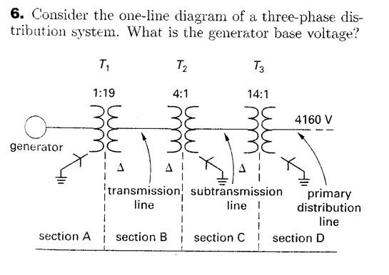
The solution has the sqrt3 conversions in it. The answer is VGen Line= 7.07 kV
How is it different from #118?
Thanks for your time.
Flyer_PE
Jr. PE / Sr. Company Pilot
^The way that problem is presented, I would answer that the generator line voltage is 12.3 kV. If they don't tell you that the turns ratio given is for the individual transformers in the 3-phase bank, the turns ratio is assumed to be in terms of VLine on both sides of the transformer.
BamaBino
Well-known member
This is Camera's solution.^The way that problem is presented, I would answer that the generator line voltage is 12.3 kV. If they don't tell you that the turns ratio given is for the individual transformers in the 3-phase bank, the turns ratio is assumed to be in terms of VLine on both sides of the transformer.
Is it incorrect?
BamaBino
Well-known member
In #118, we are given that the Vline of the Generator in delta-configuration is 13.2 kV. If the problem asked for the Vphase of the Generator, the answer would be 7.97 kV, correct?
palvarez83
Project Engineer
Camera's solution is correct. For 3 phase transformers, if they present you with ratios like this problem does they are winding ratios. However on each side of the transfomers line voltages are reported (unless stated otherwise). Winding ratios are always equal to the ration of phase voltages that is (N1/N2)= (Vphase1/Vphase2). For a delta-wye xfmr, for the delta side, the line voltage is the same as the phase voltage. However for the wye side, the phase voltage = Vline/sqrt(3). Therefore just work you way back. Since they start with a wye connect winding where they give you 4160v, you have to divide by sqrt 3 = 2,402V. That's the phase voltage of the secondary side of T3. The multiply by the winding ration 2402 x (14/1) = 33,625V. That's the phase voltage of primary side of T3 which is the same as the line voltage of section C. Next, because T2 also has a wye connected winding on the secondary side, you have to first divide by srt(3) to get the phase voltage ect...This is Camera's solution.^The way that problem is presented, I would answer that the generator line voltage is 12.3 kV. If they don't tell you that the turns ratio given is for the individual transformers in the 3-phase bank, the turns ratio is assumed to be in terms of VLine on both sides of the transformer.
Is it incorrect?
Conclusion: Camera's solution is correct.
palvarez83
Project Engineer
I'm getting Vphase = 13.2kv / srt(3) = 7.62kvIn #118, we are given that the Vline of the Generator in delta-configuration is 13.2 kV. If the problem asked for the Vphase of the Generator, the answer would be 7.97 kV, correct?
palvarez83
Project Engineer
^The way that problem is presented, I would answer that the generator line voltage is 12.3 kV. If they don't tell you that the turns ratio given is for the individual transformers in the 3-phase bank, the turns ratio is assumed to be in terms of VLine on both sides of the transformer.
I don't quite agree with this. For 3 phase if they give you a ratio such as 1:10. That is gonna be the ratio of the individual windings. The first nubmer is the primary and the second number is the secondary. However for 3 phase transformers they usually tell you the line voltage of each side (e.g. 13.2 - 132 kV). Here again the first number is the primary line voltage and the second number is the secondary line voltage. As you can see in this example I gave the line voltage ratio is the same ase the winding ratio if it's a single phase, delta-delta, or wye-wye.
However, the if it is a wye-delta or a delta-wye that is not the case. In this situation the Line voltage of the wye connected windings has to be divded by srt(3) to get the phase voltage. Therefore the ratio of the line voltage (delta side) to phase voltage (wye side) is equal to the winding ratios.
Side Note: When you see a transformer data such as 50MVA, 13.2 -132 kv, X = 10%, These voltages are the rated voltages for that transformer (not necessarily the actual voltages of the system). That is the 10% is per unit reactance on each side of the transformers using 50MVA as your base power and either 13.2 or 132 kv as your base voltage (depending what side you are referencing). When used with another base power or on another voltage say, 240V -2400V (same voltage ratios), the per unit rectance would have to be converted the the new base power and voltage.
Flyer_PE
Jr. PE / Sr. Company Pilot
I think this is a clash between the class room and the real world. I don't recall ever seeing the turns ratio for the individual transformers in a three-phase bank on a transformer name plate. The only time I've ever seen it presented like this is in a text book where they are trying to teach basic three-phase theory. If I were writing that problem, I would add a few more words to clarify the information given. If their objective is to see if you understand how a three-phase bank actually works and can do the delta-wye conversions, another sentence clearly indicating you are looking at the turns ratios for the individual windings wouldn't hurt.^The way that problem is presented, I would answer that the generator line voltage is 12.3 kV. If they don't tell you that the turns ratio given is for the individual transformers in the 3-phase bank, the turns ratio is assumed to be in terms of VLine on both sides of the transformer.
I don't quite agree with this. For 3 phase if they give you a ratio such as 1:10. That is gonna be the ratio of the individual windings.
palvarez83
Project Engineer
I absolutely agree, that it is a clash between class room world and real world, and yes, turns ratios aren't reported on the nameplate because quite frankly installing electricians don't care and many would not understand. However, the originator of this topic asked about a specific exam practice problem. Given that its is an engineer's exam preparation forum, not an installing electrician's forum, the "class room" world should take precedence. I answered this question how those problems are written both on practice problems and the real exam. Let's say that this soon to be Electrical PE were not to be designing electrical systems but rather components, such as transformers, he/she would have to understand things this way.I think this is a clash between the class room and the real world. I don't recall ever seeing the turns ratio for the individual transformers in a three-phase bank on a transformer name plate. The only time I've ever seen it presented like this is in a text book where they are trying to teach basic three-phase theory.^The way that problem is presented, I would answer that the generator line voltage is 12.3 kV. If they don't tell you that the turns ratio given is for the individual transformers in the 3-phase bank, the turns ratio is assumed to be in terms of VLine on both sides of the transformer.
I don't quite agree with this. For 3 phase if they give you a ratio such as 1:10. That is gonna be the ratio of the individual windings.
Last edited by a moderator:
Complex Imaginary
Member
palvarez83 is correct, and emphasizes a very important point. The way we discuss these things in the industry and conversationally is VERY different than how it should be understood for the purpose of this exam. For the exam, you have to think the way that palvarez83 is describing: academically. If you try to make sense out of the industry lingo and apply it to exam problems, you will often get yourself confused. A lot of people fail multiple times because of this. They wonder "I'm a good, successful engineer with plenty of experience; why don't I get this?" It's because they are two different things.
The PE test will get you with all that phase/line values, root-3 issues, delta-wye connections stuff. A delta-wye transformer is very common, so people often talk about the load side current, without specifying line or phase. Well, that's because there's no difference for a wye connection. So you get away with it in conversation if most load side connections are wye configured. BUT...the PE exam will set you up with a delta-delta transformer, and in your mind, you will have to fight against the rule-of-thumb principle that you are so used to, and has become an unthinking assumption. So you REALLY have to visualize the setup of the problem and throw your assumptions out.
My company is actually producing a series of root 3 videos that apply to these concepts. They are being uploaded to the web at a pace of about 1 video every 3-4 days. You can check out the first two videos here:
I hope these help ... and more are on the way.
Josh
Complex Imaginary
The best Power PE prep available
http://www.compleximaginary.com
Similar threads
- Replies
- 0
- Views
- 662
- Replies
- 2
- Views
- 2K
- Replies
- 0
- Views
- 357

