rg1
Well-known member
I hope the explanation makes sense. I have never dealt with grounding winding of a transformer because I have never worked in a ungrounded system, I mean it is really funny to have undergrounded system and then ground it by a separate wdg. However the concept is no rocket science, I must have understood it rightly. Discussion welcome.Here is the text:
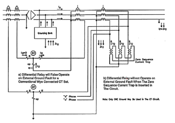
In our example, the transformer has the Δ-Y connection. Traditionally, CTs on the Wye connected transformer winding (winding 2) are connected in a delta arrangement, which compensates for the phase angle lag introduced in the Delta connected winding (winding 1), so that line currents from both windings can be compared at the relay. The Delta connection of CTs, however, inherently has the effect of removing the zero sequence components of the phase currents. If there is a grounding bank on the Delta winding of the power transformer within the zone of protection, (IMHO this situation can be imagined same as star connected wdg with ground, on main Delta wdg side too- So the situation becomes like this - Both sides, primary and secondary of the Xmer are star with grounded neutral- and the CTs on one side are star connected (because main wdg is delta) and other side it is delta connected. In such a case the zero sequence currents on star connected CTs will flow through the Operating coil of the relay. In this case you will have diff relay tripping on through L-G faults because they give rise to zero sequence currents in the star connected CTs. To avoid this the traditional method is to connect both side CTs in delta connection, attached is the diagram for connection. This is called marketing strategy of T60, nothing else- as if till digital relays were not there, we were without electricity). a ground fault results in differential (zero sequence) current and false trips. In such a case, it is necessary to insert a zero sequence current trap with the Wye connected CTs on the Delta winding of the transformer.
This is a very special case. If there weren't so many special cases we wouldn't need engineers.")
View attachment 9987