robertplant22
Active member
- Joined
- Feb 1, 2012
- Messages
- 38
- Reaction score
- 1
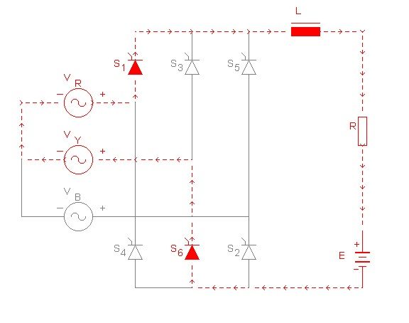
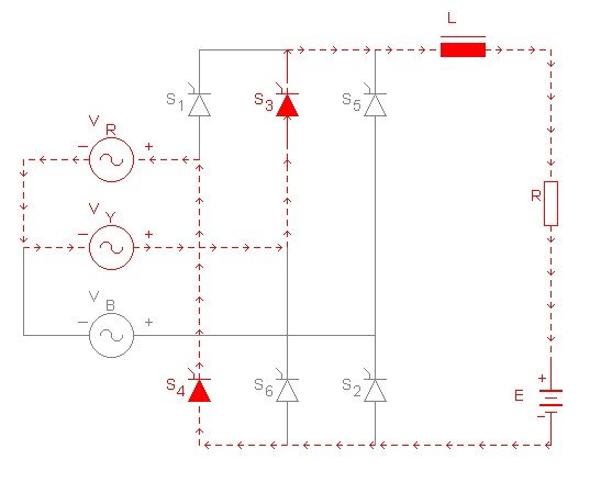
I do not understand why the answer is (D). If the circuit is functioning as a single phase full wave rectifier, the output current would be similar to that of the voltage output waveform; which is, waveforms with only positive values as shown below.
For anyone who is wondering where the picture came form; it came from the book Electrical Machines, Drives, and Power Systems pg. 482
For anyone who is wondering where the picture came form; it came from the book Electrical Machines, Drives, and Power Systems pg. 482