NCEES #519

Professional Engineer & PE Exam Forum

Help Support Professional Engineer & PE Exam Forum:

This site may earn a commission from merchant affiliate links, including eBay, Amazon, and others.

robertplant22

Active member
Joined
Feb 1, 2012
Messages
38
Reaction score
2
I do not understand why the answer is (D). If the circuit is functioning as a single phase full wave rectifier, the output current would be similar to that of the voltage output waveform; which is, waveforms with only positive values as shown below.

For anyone who is wondering where the picture came form; it came from the book Electrical Machines, Drives, and Power Systems pg. 482
Have a look at this thread and see if it helps.

 
Not sure why the picture did not upload, but here it is. I read the thread knight1fox3 pointed to; but I'm still confused. In the graph below, the current never goes below 0; were as in the answer given in the NCEES book it does.

Full Wave Single Phase Rectifier.PNG

 
For this particular problem, I don't think that graph is helpful.

To quote another poster in that thread, the key here is understanding what is actually being asked.

I think the key to this problem is understanding what is asked. The problem asks ONLY for PHASE A. Not for the circuit.

Second part is understanding that PHASE A will (1) have one peak over a cycle, 1/60s, and (2) one negative peak as it will carry the return current from phase B.
 
Can someone explain why it is D and not B? Why is the waveform not sinusoidal?

 
Since the motor load is nonlinear, the phase current waveform will not be sinusoidal. So you can quickly discount B.

For one cycle, diodes connected to Phase A will only conduct between 0 and 60 degs (+ve) and 120-240deg (-ve). As the circuit is not filtered by an inductor, the distortion factor factor will be high and DC current will contain high order harmonics. This will make the waveform look like a short impulse as shown in the answer and not the square wave you are used to seeing. So the only answer that makes sense is D.

I don't see how blown Fuse F3 has any impact on the current waveform. The phase voltages will be unbalanced but the current Ia waveform essentially remains the same ( magnitude will change) as far as I can see. Maybe someone can comment on that.

 
For this particular problem, I don't think that graph is helpful.

To quote another poster in that thread, the key here is understanding what is actually being asked.

I think the key to this problem is understanding what is asked. The problem asks ONLY for PHASE A. Not for the circuit.

Second part is understanding that PHASE A will (1) have one peak over a cycle, 1/60s, and (2) one negative peak as it will carry the return current from phase B.
Can someone please clarify the latter portion of the second statement in the above quote: "and (2) one negative peak, as it will carry the return current from phase B".

I can't seem to grasp my mind around this, on how conceptually this is happening. Thanks!

 
Thanks Knight, that was a very helpful link!

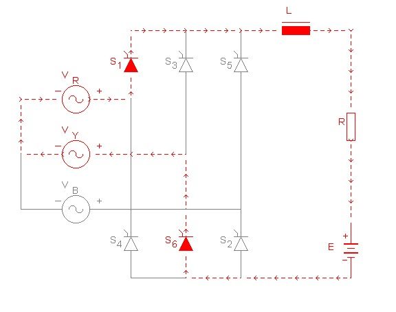
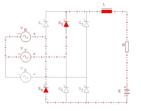
So just to reinforce the point I took (2) screen shots, let me know if my below explanation conforms to the solution's explanation.

Lets assume V_R is V_A from problem #519, and V_Y is V_B from problem #519. Now, the first image displays the positive peak phase A will see and the second image displays the negative peak phase A will see (the return current from Phase B). Is that correct?

PositivePeak_zpse1521d0c.jpg


NegativePeak_zpsc6fe742c.jpg
Hi K-Nova where did you take these shots from? I mean source? I would want to read that too. Please tell me the source book or a web link if you dont mind. Thanks in advance

 
Back
Top