
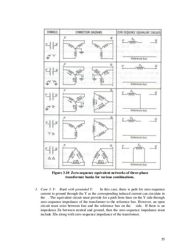
It's not clear to me how to interpret whether current will flow through (or in) a piece of equipment e.g. XFMR) given its sequence diagram. Specifically, zero sequence is confusing me, because my understanding is that it has to involve ground (is that accurate or a misnomer?). Refer to the diagrams below. Generally speaking, are we looking to see whether there's a connection between P and Q? Between P and ground? Between Q and ground? How exactly do you read these?
For example:
Item #1 -- Grounded Wye-Ungrounded Wye -- There's no connection between P and Q, so this means no zero sequence current will flow through the XFMR?
Item #3 -- Grounded Wye-Delta -- The Camara book says that a Delta secondary will permit zero sequence current, but the diagram below (3rd from top) shows a connection between the Primary winding and ground. Does this mean that zero sequence only flows on the primary side for a fault on the primary? That is, if there's a fault on the Delta secondary, no zero sequence current will by supplied from the primary side, therefore no zero sequence current will exist?
Thanks!
If the image below doesn't appear, here's a link http://image.slidesharecdn.com/unit1-8-140301074701-phpapp01/95/unit1-8-55-638.jpg There are similar diagrams in Camara on p36-13.

