Electrical PE Review Practice Exam

Professional Engineer & PE Exam Forum

Help Support Professional Engineer & PE Exam Forum:

This site may earn a commission from merchant affiliate links, including eBay, Amazon, and others.

Byk

Well-known member
Joined
Jul 21, 2020
Messages
63
Reaction score
13
I was wondering if anyone went trough this exam and found any errors. There are few answers that simply do not make sense.

Also, am I the only one who feels that the exam was written with a "gotcha" intent?

For the reference I was working with version 1.0.5

 
I have the exam, though it is an earlier version.

The author of the exam also visits and peruses this board. I confirmed with him that there are no major changes between the early version I have, and the latest version.

Which specific questions are you having trouble with on the Electrical PE Review exam?
I see, thank you for the info.

I do not understand question 32 when it asks to calculate the percent impedance of the generator.

I do not get why are we to use 15kV as a new Vbase.

 
I see, thank you for the info.

I do not understand question 32 when it asks to calculate the percent impedance of the generator.

I do not get why are we to use 15kV as a new Vbase.
I have it in front of me and am looking at 32.

The question states that the system voltage base at the distribution bus (all the way downstream) is equal to the secondary voltage rating of transformer T2, the most downstream transformer.

So then you have to work upstream converting the voltages via the turn ratios to get the system generator base voltage:

V dist bus, base = 69 KV

V transmission, base = 69 KV * 230/69 = 230 KV

V gen, base = 230 KV * 15/230 = 15 KV

This 15 KV also represents the new voltage base for the generator, when you are asked to convert the generator's p.u. impedance to the system base.

The generator's old base voltage is the rated voltage, which is the 13.8 KV given at the generator.

The formula for converting p.u. impedance to a new system base is:

Z pu new = Z pu old * (S base new / S base old) * (V base old / V base new)^2

So the (Vbase old / V base new)^2 = (13.8 KV / 15 KV)^2

Hope this helps.

 
Also I think I should mention the rules for setting a system base.

When you are given a base power (VA) value to use, this base power applies to the entire system (regardless of transformers in the system).

When you are given a base voltage value and there are transformers in the system, the base voltage will be transformed via the turns ratio of the transformer.

So in problem 32, the distribution zone's base voltage is given as 69 KV, and calculating with the given transformer turns ratios, the transmission zone's (middle zone's) base voltage is 230 KV, and the generator zone's base voltage is 15 KV.

 
I have it in front of me and am looking at 32.

The question states that the system voltage base at the distribution bus (all the way downstream) is equal to the secondary voltage rating of transformer T2, the most downstream transformer.

So then you have to work upstream converting the voltages via the turn ratios to get the system generator base voltage:

V dist bus, base = 69 KV

V transmission, base = 69 KV * 230/69 = 230 KV

V gen, base = 230 KV * 15/230 = 15 KV

This 15 KV also represents the new voltage base for the generator, when you are asked to convert the generator's p.u. impedance to the system base.

The generator's old base voltage is the rated voltage, which is the 13.8 KV given at the generator.

The formula for converting p.u. impedance to a new system base is:

Z pu new = Z pu old * (S base new / S base old) * (V base old / V base new)^2

So the (Vbase old / V base new)^2 = (13.8 KV / 15 KV)^2

Hope this helps.
So we cannot use Zpu new=Zp old * (Snew/Sold) because of zone 2?

On the other hand I also tough of converting pu to actual value of the generator and then back to pu using Zbase at the T2 but that did not work either.

 
Also I think I should mention the rules for setting a system base.

When you are given a base power (VA) value to use, this base power applies to the entire system (regardless of transformers in the system).

When you are given a base voltage value and there are transformers in the system, the base voltage will be transformed via the turns ratio of the transformer.

So in problem 32, the distribution zone's base voltage is given as 69 KV, and calculating with the given transformer turns ratios, the transmission zone's (middle zone's) base voltage is 230 KV, and the generator zone's base voltage is 15 KV.
Why wouldn't you use 13.8kV as Vbase for the Generator?

 
Why wouldn't you use 13.8kV as Vbase for the Generator?
The problem statement specifically stated to use another voltage value as the voltage base - the 69 KV voltage as the base on the distribution zone, then converted through the two transformers' turn ratios to get the 15 KV base voltage at the generator that you're supposed to use for the generator system base.

Basically the problem is telling you to use another base value as the system base value, instead of the 13.8 KV given at the generator.

 
So we cannot use Zpu new=Zp old * (Snew/Sold) because of zone 2?

On the other hand I also tough of converting pu to actual value of the generator and then back to pu using Zbase at the T2 but that did not work either.
You can still (and you are supposed to) use Z pu new = Z pu old * (S base new/S base old) * (Vbase old/V base new)^2. You just need to make sure you are using the correct base voltage value, keeping in mind that each transformer changes the base voltage value between different zones.

 
You can still (and you are supposed to) use Z pu new = Z pu old * (S base new/S base old) * (Vbase old/V base new)^2. You just need to make sure you are using the correct base voltage value, keeping in mind that each transformer changes the base voltage value between different zones.
My problem was that I ignored zone 2 and how that will effect the base values.

Thanks for the help @akyip.

 
Last edited by a moderator:
Also, am I the only one who feels that the exam was written with a "gotcha" intent?
I totally get where you're coming from. I haven't taken Zach's course myself, but due to the overwhelmingly positive reviews of Zach's course and exam, I saved this exam as one of the last unseen exams I was going to time myself on. Half way through the morning section, I realized I was burning through a lot of time reading and re-reading questions just trying to understand the wording and how I was going to setup the problem, maybe this is partially because I didn't take his course and had to really parse out the sentences in each problem. I feel some of the problems requiring the NEC code required way more time than I would've expected. I found myself wondering if the nuances the exam gets into are helpful or distracting, but he eventually does a good job explaining things in the solutions that I walk away thinking this will probably be helpful to know, even if I did sink way more time than I wanted to on the problem. I eventually stopped digging into every problem I was confused about and thought I would research later if I had time and maybe email Zach about them later or post here. Since you made the post, I'll post a few things I was wondering about here:

Problem #3: the integration uses both a starting and ending angle. Is this unique to IGBTs because SCRs conduct until the end of the cycle so ending angle is always 180 degrees

Problem #6: Do all inverse time curves look like this? Google search brought up some inverse time curves that look like below, but I can't tell if its for different pickup settings or not.

   image.png

 
Last edited by a moderator:
I totally get where you're coming from. I haven't taken Zach's course myself, but due to the overwhelmingly positive reviews of Zach's course and exam, I saved this exam as one of the last unseen exams I was going to time myself on. Half way through the morning section, I realized I was burning through a lot of time reading and re-reading questions just trying to understand the wording and how I was going to setup the problem, maybe this is partially because I didn't take his course and had to really parse out the sentences in each problem. I feel some of the problems requiring the NEC code required way more time than I would've expected. I found myself wondering if the nuances the exam gets into are helpful or distracting, but he eventually does a good job explaining things in the solutions that I walk away thinking this will probably be helpful to know, even if I did sink way more time than I wanted to on the problem. I eventually stopped digging into every problem I was confused about and thought I would research later if I had time and maybe email Zach about them later or post here. Since you made the post, I'll post a few things I was wondering about here:

Problem #3: the integration uses both a starting and ending angle. Is this unique to IGBTs because SCRs conduct until the end of the cycle so ending angle is always 180 degrees

Problem #6: Do all inverse time curves look like this? Google search brought up some inverse time curves that look like below, but I can't tell if its for different pickup settings or not.

   View attachment 20496
I can't really answer for 6, but I will answer for 3.

Yes, the integration from theta 1 to theta 2 is unique/exclusive to IGBTs. They have both a firing angle for starting conducting and a firing angle for stopping conducting. It's a step up for controlling firing, from SCRs which only control starting the conducting.

 
Last edited by a moderator:
I totally get where you're coming from. I haven't taken Zach's course myself, but due to the overwhelmingly positive reviews of Zach's course and exam, I saved this exam as one of the last unseen exams I was going to time myself on. Half way through the morning section, I realized I was burning through a lot of time reading and re-reading questions just trying to understand the wording and how I was going to setup the problem, maybe this is partially because I didn't take his course and had to really parse out the sentences in each problem. I feel some of the problems requiring the NEC code required way more time than I would've expected. I found myself wondering if the nuances the exam gets into are helpful or distracting, but he eventually does a good job explaining things in the solutions that I walk away thinking this will probably be helpful to know, even if I did sink way more time than I wanted to on the problem. I eventually stopped digging into every problem I was confused about and thought I would research later if I had time and maybe email Zach about them later or post here. Since you made the post, I'll post a few things I was wondering about here:

Problem #3: the integration uses both a starting and ending angle. Is this unique to IGBTs because SCRs conduct until the end of the cycle so ending angle is always 180 degrees

Problem #6: Do all inverse time curves look like this? Google search brought up some inverse time curves that look like below, but I can't tell if its for different pickup settings or not.

   View attachment 20496
I think overall exam is very good, it makes you go a couple steps further then actually needed for the actual exam. But I think it's good since you get a lot more practice.

Regrading question 6:

I want to say that the graph will vary from manufacturer to manufacture but the overall principal stays the same.

I believe that Zack was going here more for the basics which is that  CB will have less time delay when going from inverse to very inverse.

Here is what I printed from ABB (it might help to compare the graphs) 

https://sertecrelays.net/wp-content/uploads/2019/02/41-100.1B.pdf

 
I think overall exam is very good, it makes you go a couple steps further then actually needed for the actual exam. But I think it's good since you get a lot more practice.
Agree 100%

 
I was wondering if anyone went trough this exam and found any errors. There are few answers that simply do not make sense.

Also, am I the only one who feels that the exam was written with a "gotcha" intent?

For the reference I was working with version 1.0.5
I believe @Zach Stone, P.E. does tend to write many of his questions with a few tricks thrown in to better prepare you for the exam. It is possible that NCEES could do the same with certain problems by giving you extra information in the problem statement or giving incorrect solutions with common errors like an incorrect sign or using line voltage value that should be phase voltage. It is really testing your understanding of the fundamentals of each topic, which is really the basis of the exam.

 
Last edited by a moderator:
Another question, on Problem #53:

The correct answer includes "a portable GFCI cord" according to 590.6(A)(1). Below is this section

image.png

My initial reading of this section made it made me think the outlet itself must have a mandatory GFCI, the portable stuff is optional. Anyone else read it that way?

 
Last edited by a moderator:
Another question, on Problem #53:

The correct answer includes "a portable GFCI cord" according to 590.6(A)(1). Below is this section

View attachment 20505

My initial reading of this section made it made me think the outlet itself must have a mandatory GFCI, the portable stuff is optional. Anyone else read it that way?
Portable cord is just a part of the answer. If you read the whole answer it says GFCI receptacle first.

 
Last edited by a moderator:
Portable cord is just a part of the answer. If you read the whole answer it says GFCI receptacle first.
If portable cord is permitted "in addition" to the other mandatory GFCI requirements, then isn't the answer (B) and not (A)? The only difference between (B) and (A) is the portable cord.

 
Last edited by a moderator:
I work in construction, so I am very familiar with this section. Note this is only for temporary use on construction sites and does not meet the requirements for permanent GFCI protection of receptacles required in 210.8.

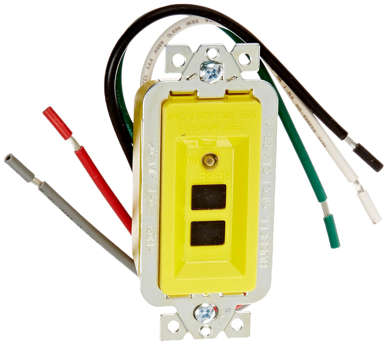
The last part of 590.6(A)(1) & (2) states that listed cord sets or devices incorporating listed GFCI protection shall be permitted to meet the GFCI requirement such as the one shown below. The three other methods that I have seen, and allowed by this code, is possible such as using GFCI-type receptacles as the temporary receptacle, installing GFCI modules at some point in the line (shown in the second picture below), or using GFCI type breakers at the panel. Based on this, I agree that the correct answer is (A).

yellow-tower-manufacturing-corporation-general-purpose-cords-30438036-01-64_1000.jpg


7167O9WWYiL._SL1500_.jpg


Thanks @Dothracki PE I guess I'm continuing to read the code wrong. I pulled open my NEC handbook and saw that this part of the code had changed so I thought perhaps the solution was a remnant of a previous code version. My reading is that the 2014 code allows for portable cords only, and the 2017 code allows for portable cords in addition to other requirements, which to me means you need other GFCI whether you have portable cords or not, which would mean Solution (A) is incorrect. Thanks for the expert input 👍 I think I've spent enough time on this problem lol


Latest posts

Back
Top