
Zach Stone P.E.
Well-known member
I've been getting a lot of questions lately from students in our online program about the Two Wattmeter Method. Typically, these problems are very easy to solve if the system is balanced.
However, if the system is unbalanced it can be quite difficult to derive the correct formula depending on how both wattmeters are connected.
I figured if our students have been scratching their heads on this one, then a lot others probably have been too.
Here are three new YouTube videos published today taken directly from the recording of last semester's live class. I hope this helps and please feel free to ask any questions in the thread.
The full article where this information comes from can be found here: https://www.electricalpereview.com/3-steps-for-solving-the-two-method-wattmeter-problem/
______
3 Steps for Solving the Two Method Wattmeter Problem:
Contents:
/monthly_2020_05/1653897752_Ch.1MeasurementandInstrumentation(3)(1).png.f9dcf99a469d73698fb3652782c5aa85.png
1. Basic Rules, Circuit and Formula P = W1 + W2 (Two Method Wattmeter)
In Part 1 of the Two Method Wattmeter series, we are going to show you:
1. The three "rules" for using two wattmeters to measure the total power of a three-phase balanced or unbalanced circuit
*For example: if the negative (-) voltage reference for wattmeter 1 (W1) is on C phase, then the negative (-) voltage reference for wattmeter 2 (W2) MUST also be on C phase.
Rule #1 - The negative (-) voltage reference for both wattmeters MUST be on the same phase (both on A, B, or C).
Rule #2 - The line current measured on each phase MUST be the same phase as the positive (+) voltage reference for each wattmeter! *For example, if the positive (+) voltage reference for wattmeter 1 (W1) is on A phase, then wattmeter 1 (W1) MUST ALSO measure the line current on A phase.
Rule #3 - The positive (+) voltage reference for both wattmeters MUST NOT be on the same phase!
*For example: if the positive (+) voltage reference for wattmeter 1 (W1) is on A phase, then the positive (+) voltage reference for wattmeter 2 (W2) MUST NOT be on A phase.
2. How to derive the two method wattmeter formula commonly seen in books depending on which phases the positive (+) and negative (-) voltage polarity for wattmeter 1 (W1) and wattmeter 2 (W2) are connected to:
P3ø = W1 + W2
In the configuration that wattmeter 1 (W1) and wattmeter 2 (W2) are shown connected in this video, we can expand this formula into:
P3ø = |VAC|·|Ia|·cos(θ-30º) + |VBC|·|Ib|·cos(θ+30º)
2. Phasor Diagrams and Solving for W1 and W2 (Two Method Wattmeter)
In Part 2 of the Two Method Wattmeter series, we are going to show you:
1. How to draw the phasor diagram for both wattmeter 1 (W1) and wattmeter 2 (W2) depending on how each wattmeter is connected according to the three "RULES" from Part 1.
The phasor diagrams will depend on which phases the positive (+) and negative (-) voltage polarity are connected to for wattmeter 1 (W1) and wattmeter 2 (W2).
2. How to easily derive the correct power angle (θ) for both wattmeter 1 (W1) and wattmeter 2 (W2) graphically using both of the phasor diagrams we set up.
*Here's the trick! One of the line voltages being measured by either wattmeter 1 (W1) or wattmeter 2 (W2) depending on how they are connected will be NEGATIVE (CBA) SEQUENCE, and one will be positive (ABC) sequence.
*Inside the cosine function in the power formula, one of the wattmeters will have θ MINUS thirty degrees while the other will have θ PLUS thirty degrees depending on how both wattmeters are connected:
cos(θ-30º)
cos(θ+30º)
3. Shortcuts and Tricks (Two Method Wattmeter)
In Part 3 of the Two Method Wattmeter series, we are going to show you:
1. How to quickly identify which of the two wattmeters (W1 or W2) has the θ MINUS thirty degrees inside the cosine function, and which has the θ PLUS thirty degrees inside the cosine function WITHOUT taking the time to draw out the phasor diagrams.
*It's extremely important to know how to draw both of the phasor diagrams (Part 2 in the Two Method Wattmeter Series) and how to derive the power formula commonly see in books (Part 1 in the Two Method Wattmeter Series) because in doing so you'll be able to answer just about any and every two method wattmeter question on the Electrical Power PE Exam.
*HOWEVER! Time is really important during the exam because you only have a certain amount of time to answer each question.
*Because of this, sometimes it is helpful to know how to QUICKLY identify which wattmeter the cos(θ-30º) and cos(θ+30º) terms belong to.
2. If the system is positive sequence (ABC), look for the negative sequence voltage.
In a positive sequence (ABC) system:
The A line voltage is measured from A to B (VAB)
The B line voltage is measured from B to C (VBC)
The C line voltage is measured from C to A (VCA)
In the example circuit used in the video, wattmeter 1 (W1) is connected across A (+) to C (-).
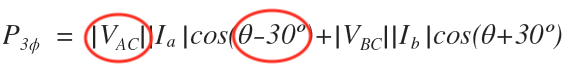
The line voltage that wattmeter 1 (W1) is measuring is the negative sequence C line voltage (VAC), NOT the positive sequence C line voltage (VCA).
This means that the formula for the power measured by wattmeter 1 (W1) will have the 30º minus theta term inside the cosine function:
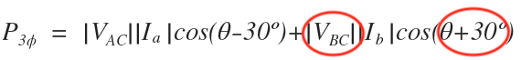
In comparison, in the example circuit used in the video, wattmeter 2 (W2) is connected across B (+) to C (-).
The line voltage that wattmeter 2 (W2) is measuring is the positive sequence B line voltage (VBC).
This means that the formula for the power measured by wattmeter 2 (W2) will have the 30º plus theta term inside the cosine function:
The wattmeter (W1 or W2) that has the 30º minus theta term inside the cosine function and the wattmeter (W1 or W2) that has the 30º plus theta term inside the cosine function always depends on how the wattmeters are connected.
There will always be one wattmeter measuring a negative sequence line voltage, and a wattmeter that measuring a positive sequence line voltage.
If the system is balanced, it does not matter which wattmeter formula has the 30º minus theta term inside the cosine function, and which wattmeter formula has the 30º plus theta term inside the cosine function since the line voltages magnitude and line current magnitudes will be equal.
For example, if our example circuit used in the video is balanced then:
|VCA| = |VBC| = |VL| and |Ia| = |Ib| = |IL|
We can use this to simplify the two method wattmeter formula for a balanced system only:
P3ø = |VCA||Ia|cos(θ-30º) + |VBC||Ib|cos(θ+30º)
P3ø = |VL||IL|cos(θ-30º) + |VL||IL| cos(θ+30º)
P3ø = |VL||IL|[cos(θ-30º) + cos(θ+30º)]
__________________________
The full article where this information comes from can be found here: https://www.electricalpereview.com/3-steps-for-solving-the-two-method-wattmeter-problem/
However, if the system is unbalanced it can be quite difficult to derive the correct formula depending on how both wattmeters are connected.
I figured if our students have been scratching their heads on this one, then a lot others probably have been too.
Here are three new YouTube videos published today taken directly from the recording of last semester's live class. I hope this helps and please feel free to ask any questions in the thread.
The full article where this information comes from can be found here: https://www.electricalpereview.com/3-steps-for-solving-the-two-method-wattmeter-problem/
______
3 Steps for Solving the Two Method Wattmeter Problem:
Contents:
- Basic Rules, Circuit and Formula P = W1 + W2 (Two Method Wattmeter)
- Phasor Diagrams and Solving for W1 and W2 (Two Method Wattmeter)
- Shortcuts and Tricks (Two Method Wattmeter)
/monthly_2020_05/1653897752_Ch.1MeasurementandInstrumentation(3)(1).png.f9dcf99a469d73698fb3652782c5aa85.png
1. Basic Rules, Circuit and Formula P = W1 + W2 (Two Method Wattmeter)
In Part 1 of the Two Method Wattmeter series, we are going to show you:
1. The three "rules" for using two wattmeters to measure the total power of a three-phase balanced or unbalanced circuit
*For example: if the negative (-) voltage reference for wattmeter 1 (W1) is on C phase, then the negative (-) voltage reference for wattmeter 2 (W2) MUST also be on C phase.
Rule #1 - The negative (-) voltage reference for both wattmeters MUST be on the same phase (both on A, B, or C).
Rule #2 - The line current measured on each phase MUST be the same phase as the positive (+) voltage reference for each wattmeter! *For example, if the positive (+) voltage reference for wattmeter 1 (W1) is on A phase, then wattmeter 1 (W1) MUST ALSO measure the line current on A phase.
Rule #3 - The positive (+) voltage reference for both wattmeters MUST NOT be on the same phase!
*For example: if the positive (+) voltage reference for wattmeter 1 (W1) is on A phase, then the positive (+) voltage reference for wattmeter 2 (W2) MUST NOT be on A phase.
2. How to derive the two method wattmeter formula commonly seen in books depending on which phases the positive (+) and negative (-) voltage polarity for wattmeter 1 (W1) and wattmeter 2 (W2) are connected to:
P3ø = W1 + W2
In the configuration that wattmeter 1 (W1) and wattmeter 2 (W2) are shown connected in this video, we can expand this formula into:
P3ø = |VAC|·|Ia|·cos(θ-30º) + |VBC|·|Ib|·cos(θ+30º)
2. Phasor Diagrams and Solving for W1 and W2 (Two Method Wattmeter)
In Part 2 of the Two Method Wattmeter series, we are going to show you:
1. How to draw the phasor diagram for both wattmeter 1 (W1) and wattmeter 2 (W2) depending on how each wattmeter is connected according to the three "RULES" from Part 1.
The phasor diagrams will depend on which phases the positive (+) and negative (-) voltage polarity are connected to for wattmeter 1 (W1) and wattmeter 2 (W2).
2. How to easily derive the correct power angle (θ) for both wattmeter 1 (W1) and wattmeter 2 (W2) graphically using both of the phasor diagrams we set up.
*Here's the trick! One of the line voltages being measured by either wattmeter 1 (W1) or wattmeter 2 (W2) depending on how they are connected will be NEGATIVE (CBA) SEQUENCE, and one will be positive (ABC) sequence.
*Inside the cosine function in the power formula, one of the wattmeters will have θ MINUS thirty degrees while the other will have θ PLUS thirty degrees depending on how both wattmeters are connected:
cos(θ-30º)
cos(θ+30º)
3. Shortcuts and Tricks (Two Method Wattmeter)
In Part 3 of the Two Method Wattmeter series, we are going to show you:
1. How to quickly identify which of the two wattmeters (W1 or W2) has the θ MINUS thirty degrees inside the cosine function, and which has the θ PLUS thirty degrees inside the cosine function WITHOUT taking the time to draw out the phasor diagrams.
*It's extremely important to know how to draw both of the phasor diagrams (Part 2 in the Two Method Wattmeter Series) and how to derive the power formula commonly see in books (Part 1 in the Two Method Wattmeter Series) because in doing so you'll be able to answer just about any and every two method wattmeter question on the Electrical Power PE Exam.
*HOWEVER! Time is really important during the exam because you only have a certain amount of time to answer each question.
*Because of this, sometimes it is helpful to know how to QUICKLY identify which wattmeter the cos(θ-30º) and cos(θ+30º) terms belong to.
2. If the system is positive sequence (ABC), look for the negative sequence voltage.
In a positive sequence (ABC) system:
The A line voltage is measured from A to B (VAB)
The B line voltage is measured from B to C (VBC)
The C line voltage is measured from C to A (VCA)
In the example circuit used in the video, wattmeter 1 (W1) is connected across A (+) to C (-).
The line voltage that wattmeter 1 (W1) is measuring is the negative sequence C line voltage (VAC), NOT the positive sequence C line voltage (VCA).
This means that the formula for the power measured by wattmeter 1 (W1) will have the 30º minus theta term inside the cosine function:
In comparison, in the example circuit used in the video, wattmeter 2 (W2) is connected across B (+) to C (-).
The line voltage that wattmeter 2 (W2) is measuring is the positive sequence B line voltage (VBC).
This means that the formula for the power measured by wattmeter 2 (W2) will have the 30º plus theta term inside the cosine function:
The wattmeter (W1 or W2) that has the 30º minus theta term inside the cosine function and the wattmeter (W1 or W2) that has the 30º plus theta term inside the cosine function always depends on how the wattmeters are connected.
There will always be one wattmeter measuring a negative sequence line voltage, and a wattmeter that measuring a positive sequence line voltage.
If the system is balanced, it does not matter which wattmeter formula has the 30º minus theta term inside the cosine function, and which wattmeter formula has the 30º plus theta term inside the cosine function since the line voltages magnitude and line current magnitudes will be equal.
For example, if our example circuit used in the video is balanced then:
|VCA| = |VBC| = |VL| and |Ia| = |Ib| = |IL|
We can use this to simplify the two method wattmeter formula for a balanced system only:
P3ø = |VCA||Ia|cos(θ-30º) + |VBC||Ib|cos(θ+30º)
P3ø = |VL||IL|cos(θ-30º) + |VL||IL| cos(θ+30º)
P3ø = |VL||IL|[cos(θ-30º) + cos(θ+30º)]
__________________________
The full article where this information comes from can be found here: https://www.electricalpereview.com/3-steps-for-solving-the-two-method-wattmeter-problem/

