Cycle Length

Professional Engineer & PE Exam Forum

Help Support Professional Engineer & PE Exam Forum:

This site may earn a commission from merchant affiliate links, including eBay, Amazon, and others.

miloc

Project Engineer
Joined
Mar 14, 2011
Messages
77
Reaction score
0
Hi guys, I need some help with the equation used to solve a sample problem. I couldnt find it in the Cerm, HCM or Green Book. Thanks. (BTW.... 3rd time taking the exam.... gosh!)

Consider an intersection with the following characteristics:

NB: 3 lanes, total flow= 1,000 vph

SB: 3 lanes, total flow= 2,100 vph

EB: 2 Lanes, 600 vph per lane

WB: 2 Lanes, 400 vph per lane

Peak 15-min volume = 1,356 veh.

The intersection is currently signalized with a simple two-phase cycle length of 80 seconds and a total lost time of 4 seconds per phase. Assuming a saturation headway of 2.1 seconds per vehicle and a target volume to capacity ratio of 0.90, the desirable cycle length for this intersection is most nearly:

a) 77 sec

b ) 82 sec

c) 74 sec

d) 80 sec

Solution:

PHF= peak hour volume / (4* peak 15-min volume) = 5,100 / 4*1,356 = 0.94

Solve for the desirable cycle length, C (from Traffic/Transportation Engineering Text)

C=(N*TL)/(1-[Vc/{(3,600/h)*PHF*(v/c)}])

h= saturation headway, sec/veh = 2.1 sec/veh

N=number of phases= 2 phases

TL=total lost time per phase

Vc=sum of critical lane volumes = 700 + 600 = 1,300 vph (sum of maximum lane volume per phase)

v/c= volume to capacity ration = 0.90

C= 2*4/(1-[1,300/{(3,600/2.1)*0.94*(0.90)}])=77.2 sec (Answer A)

Thanks

 
miloc, you said you "need some help" but you never asked a question. What is your question?

Yes, I missed the question: I Don't know where the equation in bold fonts is coming from. I couldn't find it in my reference material. thanks.

 
miloc, you said you "need some help" but you never asked a question. What is your question?

Yes, I missed the question: I Don't know where the equation in bold fonts is coming from. I couldn't find it in my reference material. thanks.
I see. I am not 100% sure because my ITE Traffic Engineering Handbook is at work but I believe the equation you ask about is from the ITE book. I can check on Tuesday if you'd like. If it means anything, NCEES is dropping this book from its design standards starting Apr 2013.

 
The following calculations and terms are important in determining signal timing plans:


Critical Volume(Vc)

During any given signal phase, prescribed sets of traffic movements are given the right-of-way. The phase diagram shown on the Signal Operations page is a useful illustration associating sets of traffic movements to their respective phases. For each phase, one of the movements will have the maximum traffic volume per lane and this volume is known as the critical lane volume. The sum of all critical lane volumes served in a cycle is known as the critical volume (Vc).

When calculating cycle lengths and green times, it is much easier if you are working with a single type of vehicle. This is because different types of vehicles behave differently and vehicles executing different turning movements behave differently. A car turning left is generally not going to accelerate as quickly as a car going straight. Therefore, before the critical volume is calculated, it is important to make sure that all of the volumes are in through car equivalent units (tcus). TCUS are generated by multiplying the original volumes by factors to account for the added congestion that turners, both right and left, add to the traffic flow. Turners add congestion generally because they must slow down to go around the corners, and in the case of left turners, there are situations in which they block through lanes while waiting to turn. Tables with tcus factors can be found here. We must also adjust for heavy truck traffic. Trucks take more physical space on the roadway than cars, and they generally move more slowly, especially in cities. For these reasons, we must divide the volumes by a heavy vehicle factor (fHV). This factor is given by:

fhv%20eq.gif


Where %HV is the percentage of heavy vehicles.


Example

Assuming the volumes have already been factored for tcus and heavy vehicles, use the volumes for each movement shown in the figure to find the critical volume.


Solution

To find the critical volume, we must first find the critical lane volumes. This is the highest movement volume in the phase, divided by the number of lanes. The critical volume is the sum of the critical lane volumes.
critical%20ex.gif


The critical volume is: Vc =160+280+365 = 805 v.p.h.

Top

Headway (h) and Saturation Flow Rate (s)

Saturation flow rate is the number of vehicles served by a lane for one hour of green time. In order to determine saturation flow rate, we must know the headway and saturation headway. Headway is the time interval between the passage of successive vehicles moving in the same lane measured from head to head as they pass a point on the road.

Saturation headway is the headway of the vehicles in a "stable moving platoon" passing through a green light. A stable moving platoon is a group of vehicles that are traveling, but not really moving in relation to each other (i.e. all going the same speed). The headway of the first four vehicles leaving an intersection after a red light will have a higher value so the saturation headway will not be realized until the 4th or 5th queued vehicle leaves the intersection.

If every vehicle requires a time equal to the saturation headway (h), in seconds, to be serviced at a signalized intersection, then the maximum number of vehicles that can be serviced in an hour of green is given by the equation s = 3600/h, where s is saturation flow rate, in veh/hr.

Top

Lost Time

Unfortunately, intersections are not constantly in use. There may always be cars waiting for the light, but there are times when there is no one actually in the intersection. Lost time is a measure of this no-use time, and it takes into account lost time at the beginning and ends of a phase. At the beginning of the green time, actual headway will be relatively longer than saturation headway for the first four vehicles, which includes driver reaction time and the time necessary for acceleration. In the graph below, the horizontal line at "h" is the saturation headway.

startup%20losttime.jpg


Startup Lost Time Graph

The sum of the time difference between the saturation headway and the first four headways is known as start-up lost time. In addition to start-up lost time there is lost time when the right of way changes, known as clearance lost time. It is the time between the last vehicle entering the intersection and the initiation of green on the next phase.

So the total lost time (tL ) in one phase is the sum of start-up lost time and the clearance lost time and the total lost time for a cycle is the lost time per phase multiplied by the number of phases per cycle.

Top

Desired V/C Ratio (v/c)des

The v/c ratio is the ratio of current flow rate to capacity of the facility. It is an indicator of the quality of the operations at an intersection.


v/c
= (rate of flow) / capacity
v/c ratio is part of the design criteria and is a value we are hoping to attain when timing a traffic signal. To test this value at an existing intersection, we can get the flow rate from traffic counts and capacity can be calculated based on the signal timing plan.

A ratio that is greater than 1.0 predicts that the facility will fail, because it is unable to discharge the demand arriving at the section. Usually a value between 0.85 to 0.95 is considered desirable for design purposes.

Top

Peak Hour Factor (PHF)

The relation between hourly volume and the maximum probable rate of flow within an hour is defined by the peak hour factor (PHF).


PHF
= Hourly Volume / Maximum rate of flow
The Highway Capacity Manual (HCM) recommends a minimum time interval of 15 minutes for most operational and design analysis. So the PHF can be given as:

phf%20eq.gif


  • V = Peak hourly volume (veh/hr)
  • V15 = maximum 15 minute volume within the peak hour (veh).

For 15-minute periods, the maximum value of the PHF is 1.00 and the minimum value is 0.25. The normal range of values is between 0.70 and 0.98.

Top

Cycle Length Calculation

Cycle length is the amount of time from when a movement first is given the right of way until that movement receives it again. It is calculated using the equation below. Generally, agencies have some minimum cycle length below which they will not program their signals. This is because there would be too many phases per hour, and therefore too much lost time. For our examples, we will use 45 seconds as a minimum.

cyclel2.gif


  • N = Number of phases in one cycle


  • tL = Total lost time per phase (sec)


  • Vc = Critical volume (vph)


  • PHF = Peak Hour Factor


  • v/c desired = Desired volume/capacity ratio


  • h = Saturation Headway (sec)


Top


Green Time Calculations

Once the cycle length has been established, it is necessary to determine the green split, or how long each phase will have the right of way (green indication). First we must calculate the effective green time, which is the time that a movement is going, regardless of the indication shown (i.e. people going on yellow or not going at the start of a phase). Effective green time is calculated using the equation below.

effective%20green.gif


  • gi = Effective green time (sec)
  • Vci = Critical volume for phase (veh/ln·hr)
  • Vc = Total critical volume (veh/ln·hr)
  • C = Cycle Length (sec)
  • L = Total lost time (tL · N) (sec)

Actual green time is based on the effective green time, and takes into account the lost time and the all-red and yellow time to come up with a value to use in programming the signal. Actual green time is calculated using the equation below.


actual%20green.gif


  • Gi = Actual green time (sec)
  • tL = Lost time per phase (sec)
  • Yi = Yellow and all-red time (sec)


Top

Capacity

Intersection capacity is complex and involves many different factors. It is outlined in detail in the Highway Capacity Manual, but we will give it a cursory treatment.

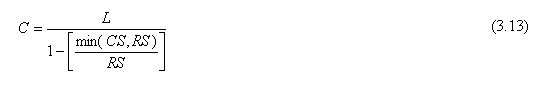
We have an equation to estimate the lane capacity at a signalized intersection. To find the approach capacity, add up the lane capacities. The equation is as follows:

capacity%20eq.gif


  • ci = Capacity of one approach lane (passenger cars per lane per hour)
  • h = Saturation headway (2 sec for our cases)
  • gi = Effective green time for the approach (sec)

    g%20eff%20from%20g%20act.gif

    Variables defined previously
  • C = Cycle length (sec)

The equation gives us the capacity in passenger cars with a normal headway. However, large trucks and turning vehicles will not necessarily have normal headways. For that reason, when we are comparing volumes to capacities (such as with the v/c ratio) we must use volumes that have been factored for heavy vehicles and turning movements.

 
PE 2009, thanks for the info. However, I think miloc is asking where in the NCEES exam design standards can the signal length, C, equation be found.

 
PE 2009, thanks for the info. However, I think miloc is asking where in the NCEES exam design standards can the signal length, C, equation be found.
Read this link.

http://ops.fhwa.dot....chapter_3p1.htm
Again, thanks. And, yes, that is good stuff. :) But I'm still curious where (if anywhere?) the "C =" formula can be found in NCEES exam design standards. The FHWA TC Systems Handbook you linked us to is not one of the NCEES standards, right? Thanks.
I expected you to read it. I copied only few lines below from above link, which talks about HCM 2000. Isn't it NCEES exam design standards?

Cycle Length and Split Settings

HCM 2000 (10) provides a detailed description of computational procedures for cycle and split settings. The following discussion summarizes some of the key items in the HCM. Please read link carefully.

HCM 2000 provides worksheets that facilitate the estimation of critical lane volume VCL.

Following the selection of a phasing plan, critical volumes (CV) are established for each phase. These are then used to calculate the cycle as follows.

A cycle length that will accommodate the observed flow rates with a degree of saturation of 1.0 is computed by Equation A10-1 in HCM 2000 and shown in equation 3.13 below. If the cycle length is known, that value should be used.

eq3_13.jpg


where:

C = cycle length (s),

L = total lost time (s),

CS = critical sum (veh/h), flow rate

RS = reference sum flow rate (1,710 * PHF * fa) (veh/h),

PHF = peak-hour factor, and

fa = area type adjustment factor (0.90 if CBD, 1.00 otherwise).
I would expect me to read it too. The question was: where did the original "C=" formula (as contained in miloc's post #1), come from? I was currious if it could be found in an NCEES exam standard(s). The equation from the HCM above is not the same equation as post #1.

HCM is one of the NCEES exam standards. Read HCM to get it and I can't help you, if you still do not understand. Good Luck!

 
So much hostility..... I think we've got a communication block here. I'm pretty sure Ptatohed knows the HCM is one of the NCEES exam standards.... I just think his point was that the equation in the original post is not in the HCM. On the other hand, I think PE_2009 was implying that you could deduce the original equation from the one he provided from the HCM.

So, we need to get

eq3_13.jpg


where:

C = cycle length (s),

L = total lost time (s),

CS = critical sum (veh/h), flow rate

RS = reference sum flow rate (1,710 * PHF * fa) (veh/h),

PHF = peak-hour factor, and

fa = area type adjustment factor (0.90 if CBD, 1.00 otherwise).
to equal this:

C=(N*TL)/(1-[Vc/{(3,600/h)*PHF*(v/c)}])

h= saturation headway, sec/veh = 2.1 sec/veh

N=number of phases= 2 phases

TL=total lost time per phase

Vc=sum of critical lane volumes = 700 + 600 = 1,300 vph (sum of maximum lane volume per phase)

v/c= volume to capacity ration = 0.90
From the variable descriptions, we can see that:

L = the total lost time, or the total lost time per phase times the number of phases.... so L = N*TL

CS = the critical sum, or the sum of the critical lane volumes.... so CS = Vc

The problem I'm seeing is with the reference sum value, RS.

The HCM says that RS = 1710 * PHF * fa. It looks like the 1710 value is derived by dividing the unit conversion of 3600 sec/hr by the saturation headway, h, and that they are assuming a saturation headway value of 2.1. The problem is since they do not include that in the equation, it's not clear on how you would solve the original question if the saturation headway were any value other than 2.1.

The other problem I'm seeing is that the HCM equation also assumes a volume/capacity ratio of 1.0 and does not explain how to modify the equation for different ratios. The original question states that the volume/capacity ratio is 0.90.... and we can see that the equation provided in the solution shows the ratio being multiplied in the denominator, but I don't know how we would get to that conclusion from the HCM equation...

With all that being said, I don't recall there being any questions of the exam like this where I couldn't deduce an answer from the standard reference materials.

 
PE 2009, thanks for the info. However, I think miloc is asking where in the NCEES exam design standards can the signal length, C, equation be found.
Read this link.

http://ops.fhwa.dot....chapter_3p1.htm
Again, thanks. And, yes, that is good stuff. :) But I'm still curious where (if anywhere?) the "C =" formula can be found in NCEES exam design standards. The FHWA TC Systems Handbook you linked us to is not one of the NCEES standards, right? Thanks.
I expected you to read it. I copied only few lines below from above link, which talks about HCM 2000. Isn't it NCEES exam design standards?

Cycle Length and Split Settings

HCM 2000 (10) provides a detailed description of computational procedures for cycle and split settings. The following discussion summarizes some of the key items in the HCM. Please read link carefully.

HCM 2000 provides worksheets that facilitate the estimation of critical lane volume VCL.

Following the selection of a phasing plan, critical volumes (CV) are established for each phase. These are then used to calculate the cycle as follows.

A cycle length that will accommodate the observed flow rates with a degree of saturation of 1.0 is computed by Equation A10-1 in HCM 2000 and shown in equation 3.13 below. If the cycle length is known, that value should be used.

eq3_13.jpg


where:

C = cycle length (s),

L = total lost time (s),

CS = critical sum (veh/h), flow rate

RS = reference sum flow rate (1,710 * PHF * fa) (veh/h),

PHF = peak-hour factor, and

fa = area type adjustment factor (0.90 if CBD, 1.00 otherwise).
I would expect me to read it too. The question was: where did the original "C=" formula (as contained in miloc's post #1), come from? I was currious if it could be found in an NCEES exam standard(s). The equation from the HCM above is not the same equation as post #1.

HCM is one of the NCEES exam standards. Read HCM to get it and I can't help you, if you still do not understand. Good Luck!
It's been established that the HCM is an NCEES standard, but thanks. I read the HCM and the equation is not in there as shown in post #1. I just asked a simple question. If you can't answer it or if you don't understand what I am asking, that's fine. It's not that big of a deal.

I don't need luck (already passed), but thanks anyway. ;)

 
Last edited by a moderator:
So much hostility..... I think we've got a communication block here. I'm pretty sure Ptatohed knows the HCM is one of the NCEES exam standards.... I just think his point was that the equation in the original post is not in the HCM. On the other hand, I think PE_2009 was implying that you could deduce the original equation from the one he provided from the HCM.

So, we need to get

eq3_13.jpg


where:

C = cycle length (s),

L = total lost time (s),

CS = critical sum (veh/h), flow rate

RS = reference sum flow rate (1,710 * PHF * fa) (veh/h),

PHF = peak-hour factor, and

fa = area type adjustment factor (0.90 if CBD, 1.00 otherwise).
to equal this:

C=(N*TL)/(1-[Vc/{(3,600/h)*PHF*(v/c)}])

h= saturation headway, sec/veh = 2.1 sec/veh

N=number of phases= 2 phases

TL=total lost time per phase

Vc=sum of critical lane volumes = 700 + 600 = 1,300 vph (sum of maximum lane volume per phase)

v/c= volume to capacity ration = 0.90
From the variable descriptions, we can see that:

L = the total lost time, or the total lost time per phase times the number of phases.... so L = N*TL

CS = the critical sum, or the sum of the critical lane volumes.... so CS = Vc

The problem I'm seeing is with the reference sum value, RS.

The HCM says that RS = 1710 * PHF * fa. It looks like the 1710 value is derived by dividing the unit conversion of 3600 sec/hr by the saturation headway, h, and that they are assuming a saturation headway value of 2.1. The problem is since they do not include that in the equation, it's not clear on how you would solve the original question if the saturation headway were any value other than 2.1.

The other problem I'm seeing is that the HCM equation also assumes a volume/capacity ratio of 1.0 and does not explain how to modify the equation for different ratios. The original question states that the volume/capacity ratio is 0.90.... and we can see that the equation provided in the solution shows the ratio being multiplied in the denominator, but I don't know how we would get to that conclusion from the HCM equation...

With all that being said, I don't recall there being any questions of the exam like this where I couldn't deduce an answer from the standard reference materials.
As always, good job mrt. Also, doesn't the first equation not account for the number of phases? Or am i missing something? Thanks.

 
As always, good job mrt. Also, doesn't the first equation not account for the number of phases? Or am i missing something? Thanks.
It does, just not clearly. The lost time, L, is the total lost time, not just the lost time per phase. So, to get L we need to multiply the phase lost time by the number of phases.

 
Thanks guys for all your input. Hopefully I won't see a question like this one in the exam.

 
Back
Top