Column design with eccentric beams

Professional Engineer & PE Exam Forum

Help Support Professional Engineer & PE Exam Forum:

This site may earn a commission from merchant affiliate links, including eBay, Amazon, and others.

Kelles

New member
Joined
Aug 7, 2013
Messages
3
Reaction score
0
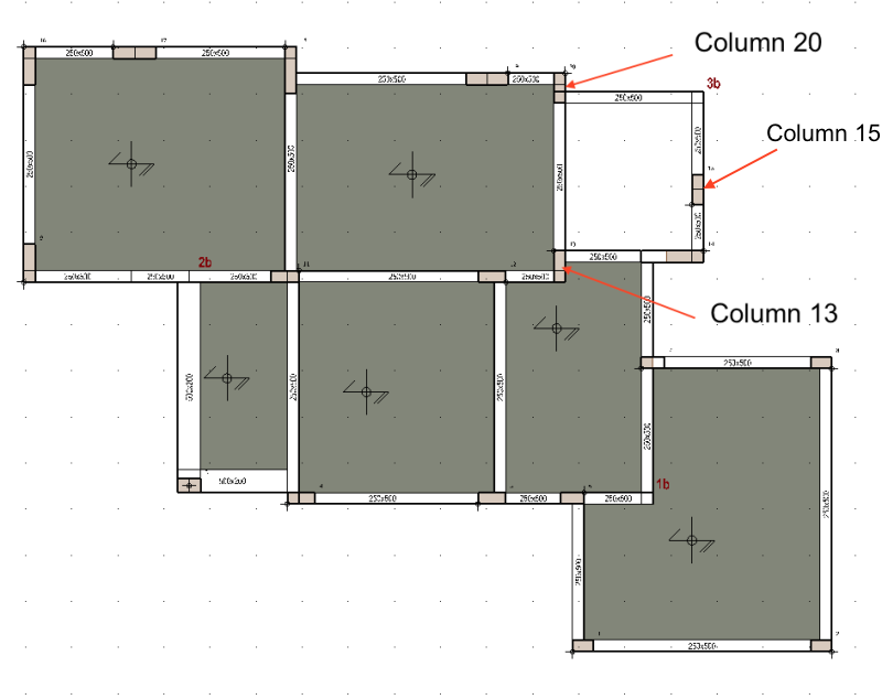
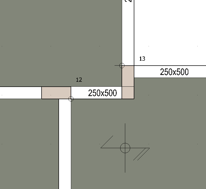
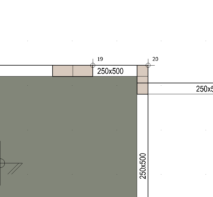
Hello everyone,I am designing a 2storey RC frame house according to EC2 and EC8 and three of the columns are impossible to design.Two of these columns 13 and 20 are of similar configuration, please see image below. They have eccentric beams connected perpendicular to the column one at each end.all columns fail at seismic load combinationsNo matter how much shear reinforcement i add or how much i increase the column section it still fails at seismic combinations.I tried researching why these 3 columns fail and i found out some excessive shear forces are generated at the seismic combinations reaching up to 1000kN in the strong axis of the column.I think this is way excessive considering the fact that this is just a 2storey house and in fact the total base shear of the structure (in the design spectrum acceleration) is only about 900kN.
 

Screen_Shot_2017-07-08_at_23.16.24_cx9kdz_zz69rg.png


Screen_Shot_2017-07-08_at_23.18.28_xb45nx.png


Screen_Shot_2017-07-08_at_23.18.39_idsieh.png


Structural design is my weak spot, but I have a few general comments regarding your problem.  

Your last statement questions the 1,000Kn load value so I'm assuming that you are relying on some sort of software to evaluate the design for you. Based on this assumption, is everything inputted into the software correctly? When using programs it is important to remember that garbage in=garbage out. In other words, if you use the wrong inputs, you are going to get the wrong results.  Have you tried confirming some of the design calculations by hand?  

 
Hello there,

I always check the results i get from the software, one way is to compare the weight of the structure between the software and hand calculations, if that is correct then not a lot could go wrong

I also check the base shear at the base of columns in order to check the earthquake input was also correct. if this two are correct then it means that all inputs are correct.

Yes i am relying on a software for the analysis, which is impossible without a software, the design i could do my self once i have the analysis results however its the analysis results which are overestimated

Thats why i am asking if people experience the same issue, in order to understand if this is a reasonable result

 
@Kelles what is EC2 and EC8?  Now, I don't agree that you need the software for the analysis. I understand this is a concrete frame, now what is your diaphragm? Is it a concrete slab? Slab on deck? The cross  in the middle of each slab makes me think it is analyzing the slab in a one way direction as if you are applying the loading to be distributed in a one way direction. However, some of those dimensions, at first glance, would make me think there is two way distribution. You have 2 spans, or it can be assumed this way, going from left to right at your second column Grid. You could do a column strip for that section manually and compare to your software. I'm not familiar with metric system, but make sure your "columns" shouldnt be designed as load bearing walls. Now, just as an FYI, Risa has free demo software for download that works perfect for limited spans and dimensions in analyzing structures. This would be Risa floor in your case, but you could get away with Risa 3D and using panels or rigid plates as flooring and just designing for the given moment. Hope this doesn't confuse anything, just trying to help. 

 
Kelles, I'm really confused by your theory about knowing the design/inputs is correct by just checking weight of structure and base shear. There seems to be more variables affecting the results such as the applied load values, joint connections, supports for floor/roof system.

 
When dealing with seismic design one of the things to note is that stiffness is one of the key components determining the distribution of forces.  One of the things that I have found is you can get yourself into a loop by increasing the size of a column which then attracts more load and increases the plastic moments - thereby causing an overload and throwing back into the loop.  Particularly when calculating plastic shear minimums this can be a problem, which is what it sounds like in your case.

I'm not sure what you are detailing, but have you thought about changing out one of the beam connections framing into the column from a fixed connection to a pinned condition?  This would probably distribute some of the forces away from that column and into other members.  Looks like particularly in the East-West direction if you kept columns 12 and 19 fixed, then 13 and 20 could be fixed in N-S and pinned or quasi-pinned (low rotational stiffness) in E-W then you could relieve some stress.  This is of course also dependent on your structure type - if using moment-frame as primary seismic resisting this is going to take more thought.

Another thought is to move the north and south walls of the northeast quadrant to be in line with the other E-W walls.  Right now it seems like E-W seismic forces would induce column torsion due to out of plane moment in the N-S "header" beam running between 13 and 20.  Adjusting this would make the system more regular, and would probably make the detailing simpler as well.

Just some suggestions.

modified framing.jpg

 
Back
Top