I am not getting this problem. Can some explain (1) why is this a series representation when transformers are paralleled, and (2) why is Va1, pertaining to one of three series impedances, the positive sequence voltage when?

You are using an out of date browser. It may not display this or other websites correctly.
You should upgrade or use an alternative browser.
You should upgrade or use an alternative browser.
NCEES Prob. # 514
- Thread starter pelaw
- Start date
Help Support Professional Engineer & PE Exam Forum:
This site may earn a commission from merchant affiliate
links, including eBay, Amazon, and others.
vbar
Member
I also don't get this one. Superstars, please help out ")
I think I figured it out.
Step 1: Determine "FAULT" -- (1) if 3 phase fault, then use symmetrical analysis, (2) if phase to ground, phase to neutral, phase to phase, then use asymmetrical analysis.
Step 2: Asymmetrical fault analysis is also called sequence analysis of faults. The analysis is done per leg under inspection.
Step 3: The sequence per leg is as followed. SEQUENCE consists of (1) POSITIVE SEQUENCE Va1, Z1, and I, (2) NEGATIVE SEQUENCE Va2, I and Z2, and (3) ZERO SEQUENCE V0, I, and Z0. The three sequences are phasors that connect from positive to negative to zero to form a system.
Step 4: draw a line with 3 impedances in series, Z1, Z2, Z0. The voltage at the end of each impedance is V1 (at Z1 terminal), V2 (at Z2 terminal), and V0 (at Z0 terminal).
Step 5: Connect that line through a loop and place the voltage source Vs at the loop. Notice now that you have the voltage source and three impedances in series. The current I is the same everywhere,
Step 6: The question asks for (1) per unit voltage of V1 (2) positive sequence only. The voltage drop over positive sequence impedance Z1 is the difference between V1 and Vs voltage. Vs voltage is the base 1.0 pu.
Step 7.: The current is the same throughout the circuit. So, the difference in voltage at positive sequence is Vs - V1 / Z1 = I. Since Vs = 1, you can plug it in. 1 -V1 / Z1 = I.
Step 8: The current I is also equal the supply voltage Vs divided by the summ of all impedances, So I = 1 pu/ (Z1 + Z2 + Z0). However, Z1 = Z2. So, I - 1/2Z1 + Z0. However, Z0 = 10 Z1. So, I = 1/12 Z1 =
Step 9: equate currents from step 7 and step 8: I = 1 - V1 / Z1 = 1/12 Z1; this leads to V1 (the positive sequence voltage) = 1 - 0.08 = 0.92 pu
Flyer_PE
Jr. PE / Sr. Company Pilot
There's a very good book by J. Lewis Blackburn: "Symmetrical Components for Power Systems Engineering". If you can find a copy, it's worth a little study on the subject.
For graphical explanation of symmetrical components, this may be helpful: Alex McEachern's Power Quality Teaching Toy.
For graphical explanation of symmetrical components, this may be helpful: Alex McEachern's Power Quality Teaching Toy.
There's a very good book by J. Lewis Blackburn: "Symmetrical Components for Power Systems Engineering". If you can find a copy, it's worth a little study on the subject.
For graphical explanation of symmetrical components, this may be helpful: Alex McEachern's Power Quality Teaching Toy.
Please please please. this problem is bugging me so much. I don't get why the postive sequence voltage simply just be the voltage IR at Z1. Also, is it safe to say that the short circuit current based on fault analysis is not the same thing as the current running through the components in series?
cableguy
Has never sniffed a stink bug
When you set up a standard single line to ground fault, you end up drawing 4 things in series. The voltage source (1pu), and then the positive, negative, and zero sequence impedances.Please please please. this problem is bugging me so much. I don't get why the postive sequence voltage simply just be the voltage IR at Z1. Also, is it safe to say that the short circuit current based on fault analysis is not the same thing as the current running through the components in series?
Now, there are no sources in the negative and zero sequences. The voltage source is associated with the positive sequence. If you draw a box around the voltage source and the positive sequence impedance - they are asking "what is the voltage of the box". This would be the voltage across the positive sequence.
We are given that the positive sequence impedance is Z, negative is Z, and zero is 10Z. So we know the current is 1 pu voltage / 12Z
We can then determine the voltage across the box. Inside the box, we have 1 per unit voltage going up, and Z * (1/12Z) going down. So we end up with .92 per unit voltage across the box.
If you don't have them already, you need to find/beg/borrow/steal symmetrical component diagrams for the different types of faults. 3 phase, single line to ground, line to line, line to line to ground, line(s) to grounds through an impedance. They all have different diagrams and they are all treated differently. And you also need to know that if the word "ground" does not appear in the fault, then you don't use the zero sequence impedance (3 phase, line to line - and there's no such thing as a 3 phase to ground fault - it's 3 phase) - even if they give it to you (which I bet they would, just to confuse you!).
Last edited by a moderator:
thanks cable guy! I think I get it now. I think the only tough part is why you would put the voltage source in a different polarity as the circuit.When you set up a standard single line to ground fault, you end up drawing 4 things in series. The voltage source (1pu), and then the positive, negative, and zero sequence impedances.Please please please. this problem is bugging me so much. I don't get why the postive sequence voltage simply just be the voltage IR at Z1. Also, is it safe to say that the short circuit current based on fault analysis is not the same thing as the current running through the components in series?
Now, there are no sources in the negative and zero sequences. The voltage source is associated with the positive sequence. If you draw a box around the voltage source and the positive sequence impedance - they are asking "what is the voltage of the box". This would be the voltage across the positive sequence.
We are given that the positive sequence impedance is Z, negative is Z, and zero is 10Z. So we know the current is 1 pu voltage / 12Z
We can then determine the voltage across the box. Inside the box, we have 1 per unit voltage going up, and Z * (1/12Z) going down. So we end up with .92 per unit voltage across the box.
If you don't have them already, you need to find/beg/borrow/steal symmetrical component diagrams for the different types of faults. 3 phase, single line to ground, line to line, line to line to ground, line(s) to grounds through an impedance. They all have different diagrams and they are all treated differently. And you also need to know that if the word "ground" does not appear in the fault, then you don't use the zero sequence impedance (3 phase, line to line - and there's no such thing as a 3 phase to ground fault - it's 3 phase) - even if they give it to you (which I bet they would, just to confuse you!).
I was looking again at this problem, and tried solving with different types of faults. If anyone has time, check my work because I'm not too confident on this subject:
If this were a 3 phase fault, we would only see the positive sequence, in which case the positive sequence voltage would be 1 pu.
It it were a line to line fault, we would see the positive and negative sequences, with currents equal in opposite directions. The current through Z1 would be 1/(Z1+Z2) leading to 0.5 pu positive sequence voltage.
If it were a double line to ground fault, we would connect all in parallel. I got the current through Z1 to be 11/21Z1, leading to a positive sequence voltage of 0.48 pu.
Am I close? Any help is appreciated. Thanks in advance!
BamaBino
Well-known member
I got the same answers as you.I was looking again at this problem, and tried solving with different types of faults. If anyone has time, check my work because I'm not too confident on this subject:
If this were a 3 phase fault, we would only see the positive sequence, in which case the positive sequence voltage would be 1 pu.
It it were a line to line fault, we would see the positive and negative sequences, with currents equal in opposite directions. The current through Z1 would be 1/(Z1+Z2) leading to 0.5 pu positive sequence voltage.
If it were a double line to ground fault, we would connect all in parallel. I got the current through Z1 to be 11/21Z1, leading to a positive sequence voltage of 0.48 pu.
Am I close? Any help is appreciated. Thanks in advance!
The 2-phase to ground fault was the difficult one. Va1 = 1 - 11/21 = 0.48 pu.
Good to hear. Thanks for the follow up!I got the same answers as you.I was looking again at this problem, and tried solving with different types of faults. If anyone has time, check my work because I'm not too confident on this subject:
If this were a 3 phase fault, we would only see the positive sequence, in which case the positive sequence voltage would be 1 pu.
It it were a line to line fault, we would see the positive and negative sequences, with currents equal in opposite directions. The current through Z1 would be 1/(Z1+Z2) leading to 0.5 pu positive sequence voltage.
If it were a double line to ground fault, we would connect all in parallel. I got the current through Z1 to be 11/21Z1, leading to a positive sequence voltage of 0.48 pu.
Am I close? Any help is appreciated. Thanks in advance!
The 2-phase to ground fault was the difficult one. Va1 = 1 - 11/21 = 0.48 pu.
dianevp
Active member
Please correct if I'm wrong, I found a formula for Ia1 to read V / (Z1 + (Z2//Z0)). The diagram shows the Z1 is in series with Z2 in parallel with Z0.I got the same answers as you.I was looking again at this problem, and tried solving with different types of faults. If anyone has time, check my work because I'm not too confident on this subject:
If this were a 3 phase fault, we would only see the positive sequence, in which case the positive sequence voltage would be 1 pu.
It it were a line to line fault, we would see the positive and negative sequences, with currents equal in opposite directions. The current through Z1 would be 1/(Z1+Z2) leading to 0.5 pu positive sequence voltage.
If it were a double line to ground fault, we would connect all in parallel. I got the current through Z1 to be 11/21Z1, leading to a positive sequence voltage of 0.48 pu.
Am I close? Any help is appreciated. Thanks in advance!
The 2-phase to ground fault was the difficult one. Va1 = 1 - 11/21 = 0.48 pu.
This makes a world of a difference.
Please advise - I'm struggling with these types of problems too.
Thanks!
My mistake on the current. I did the math right, but stated the circuit incorrectly. You are correct that Ia1=V / (Z1 + (Z2//Z0)). Good catch.
dianevp
Active member
It's better to catch them here, than on the test.Please correct if I'm wrong, I found a formula for Ia1 to read V / (Z1 + (Z2//Z0)). The diagram shows the Z1 is in series with Z2 in parallel with Z0.I got the same answers as you.I was looking again at this problem, and tried solving with different types of faults. If anyone has time, check my work because I'm not too confident on this subject:
If this were a 3 phase fault, we would only see the positive sequence, in which case the positive sequence voltage would be 1 pu.
It it were a line to line fault, we would see the positive and negative sequences, with currents equal in opposite directions. The current through Z1 would be 1/(Z1+Z2) leading to 0.5 pu positive sequence voltage.
If it were a double line to ground fault, we would connect all in parallel. I got the current through Z1 to be 11/21Z1, leading to a positive sequence voltage of 0.48 pu.
Am I close? Any help is appreciated. Thanks in advance!
The 2-phase to ground fault was the difficult one. Va1 = 1 - 11/21 = 0.48 pu.
This makes a world of a difference.
Please advise - I'm struggling with these types of problems too.
Thanks!
My mistake on the current. I did the math right, but stated the circuit incorrectly. You are correct that Ia1=V / (Z1 + (Z2//Z0)). Good catch.
Thanks for the original post, it cleared up a lot of questions I have on faults.Good Luck on Friday!
BamaBino
Well-known member
This is the tricky part of this problem, being asked to consider the positive sequence only.Step 6: The question asks for (1) per unit voltage of V1 (2) positive sequence only. The voltage drop over positive sequence impedance Z1 is the difference between V1 and Vs voltage. Vs voltage is the base 1.0 pu.
If they asked for the voltage (pu), it would be 3 times 0.917 PU.
3E = V1 + V2 + V0
Last edited by a moderator:
BamaBino
Well-known member
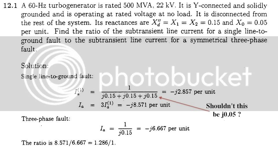
Here's a similar problems from Stevenson's book.
If they're all in parallel aren't all the voltages the same? Isn't I1 ( 11/12)Z1 not 11/21?
Man, I'm not seeing the diagram of this thing...arg.
Man, I'm not seeing the diagram of this thing...arg.
QUOTE (thewalt33 @ Apr 5 2011, 05:39 AM)
QUOTE (dianevp @ Apr 4 2011, 11:39 AM)
QUOTE (BamaBino @ Jan 21 2011, 04:50 PM)
QUOTE (thewalt33 @ Jan 20 2011, 06:54 AM)
I was looking again at this problem, and tried solving with different types of faults. If anyone has time, check my work because I'm not too confident on this subject:
If this were a 3 phase fault, we would only see the positive sequence, in which case the positive sequence voltage would be 1 pu.
It it were a line to line fault, we would see the positive and negative sequences, with currents equal in opposite directions. The current through Z1 would be 1/(Z1+Z2) leading to 0.5 pu positive sequence voltage.
If it were a double line to ground fault, we would connect all in parallel. I got the current through Z1 to be 11/21Z1, leading to a positive sequence voltage of 0.48 pu.
Am I close? Any help is appreciated. Thanks in advance!
I got the same answers as you.
The 2-phase to ground fault was the difficult one. Va1 = 1 - 11/21 = 0.48 pu.
Please correct if I'm wrong, I found a formula for Ia1 to read V / (Z1 + (Z2//Z0)). The diagram shows the Z1 is in series with Z2 in parallel with Z0.
This makes a world of a difference.
Please advise - I'm struggling with these types of problems too.
Thanks!
My mistake on the current. I did the math right, but stated the circuit incorrectly. You are correct that Ia1=V / (Z1 + (Z2//Z0)). Good catch.
It's better to catch them here, than on the test.Thanks for the original post, it cleared up a lot of questions I have on faults.
Good Luck on Friday!
Yes, it should be j0.05. If you do the math, you'll see the answer is correct (1/(.15+.15+.05) = 2.857 which is what he shows there.Here's a similar problems from Stevenson's book.
This is one of the best explanations I have read on this particular problem. Thank you!When you set up a standard single line to ground fault, you end up drawing 4 things in series. The voltage source (1pu), and then the positive, negative, and zero sequence impedances.
Now, there are no sources in the negative and zero sequences. The voltage source is associated with the positive sequence. If you draw a box around the voltage source and the positive sequence impedance - they are asking "what is the voltage of the box". This would be the voltage across the positive sequence.
We are given that the positive sequence impedance is Z, negative is Z, and zero is 10Z. So we know the current is 1 pu voltage / 12Z
We can then determine the voltage across the box. Inside the box, we have 1 per unit voltage going up, and Z * (1/12Z) going down. So we end up with .92 per unit voltage across the box.
If you don't have them already, you need to find/beg/borrow/steal symmetrical component diagrams for the different types of faults. 3 phase, single line to ground, line to line, line to line to ground, line(s) to grounds through an impedance. They all have different diagrams and they are all treated differently. And you also need to know that if the word "ground" does not appear in the fault, then you don't use the zero sequence impedance (3 phase, line to line - and there's no such thing as a 3 phase to ground fault - it's 3 phase) - even if they give it to you (which I bet they would, just to confuse you!).
knight1fox3
Jedi MASTER & Friend of Capt. Solo
Way to resurrect a 4+ year old thread! :thumbs:This is one of the best explanations I have read on this particular problem. Thank you!
Similar threads
- Replies
- 0
- Views
- 614
- Replies
- 0
- Views
- 1K
- Replies
- 0
- Views
- 280


Latest posts
-

-
-
-

-
For Sale Selling PE CIVIL Breadth and Construction Depth - EET Binders - 2023 Edition
- Latest: CivilEngineerXpert
-